Engine Assembly (For Sedan) Removal
REMOVE BATTERY
REMOVE BATTERY TRAY
REMOVE FRONT WHEELS
REMOVE ENGINE UNDER COVER LH
REMOVE ENGINE UNDER COVER RH
DRAIN ENGINE COOLANT
DRAIN AUTOMATIC TRANSAXLE FLUID (for Automatic Transaxle)
DRAIN MANUAL TRANSAXLE OIL (for Manual Transaxle)
REMOVE FRONT WIPER ARM HEAD CAP
REMOVE FRONT WIPER ARM AND BLADE
ASSEMBLY LH
REMOVE FRONT WIPER ARM AND BLADE
ASSEMBLY RH
REMOVE COWL SIDE VENTILATOR SUB-ASSEMBLY LH
REMOVE COWL SIDE VENTILATOR SUB-ASSEMBLY RH
REMOVE COWL TOP VENTILATOR LOUVER SUB-ASSEMBLY
REMOVE FRONT WIPER MOTOR AND LINK
REMOVE FRONT AIR SHUTTER SEAL RH
REMOVE COWL TOP PANEL OUTER
REMOVE AIR CLEANER ASSEMBLY
REMOVE FUEL VAPOR FEED HOSE ASSEMBLY
REMOVE AIR CLEANER BRACKET
REMOVE BATTERY CARRIER
DISCONNECT NO. 3 RADIATOR HOSE
DISCONNECT RADIATOR RESERVOIR TANK HOSE
DISCONNECT NO. 2 RADIATOR HOSE
DISCONNECT OIL COOLER OUTLET HOSE (for Automatic Transaxle)
DISCONNECT OIL COOLER INLET HOSE (for Automatic Transaxle)
REMOVE NO. 2 CYLINDER HEAD COVER
SEPARATE TRANSMISSION CONTROL CABLE ASSEMBLY (for Automatic Transaxle)
SEPARATE TRANSMISSION CONTROL CABLE ASSEMBLY (for Manual Transaxle)
DISCONNECT UNION TO CHECK VALVE HOSE
DISCONNECT HEATER WATER OUTLET HOSE A
DISCONNECT HEATER WATER HOSE INLET A
DISCONNECT FUEL TUBE SUB-ASSEMBLY
REMOVE FAN AND GENERATOR V BELT
SEPARATE COMPRESSOR ASSEMBLY WITH PULLEY (w/ Air Conditioning System)
SEPARATE CLUTCH RELEASE CYLINDER ASSEMBLY (for Manual Transaxle)
DISCONNECT ENGINE WIRE
REMOVE COLUMN HOLE COVER SILENCER SHEET
SEPARATE STEERING SLIDING YOKE SUB-ASSEMBLY
REMOVE NO. 1 STEERING COLUMN HOLE COVER SUB-ASSEMBLY
REMOVE EXHAUST PIPE ASSEMBLY FRONT
REMOVE FRONT DRIVE SHAFT ASSEMBLY
REMOVE FLYWHEEL HOUSING UNDER COVER (for Automatic Transaxle)
REMOVE DRIVE PLATE AND TORQUE CONVERTER CLUTCH SETTING BOLT (for Automatic Transaxle)
REMOVE ENGINE ASSEMBLY WITH TRANSAXLE
REMOVE FRONT SUSPENSION CROSSMEMBER SUB-ASSEMBLY
REMOVE FLYWHEEL HOUSING SIDE COVER
REMOVE STARTER ASSEMBLY
REMOVE AUTOMATIC TRANSAXLE ASSEMBLY (for Automatic Transaxle)
REMOVE DRIVE PLATE AND RING GEAR SUB-ASSEMBLY (for Automatic Transaxle)
REMOVE CONTROL CABLE BRACKET (for Manual Transaxle)
REMOVE MANUAL TRANSAXLE ASSEMBLY (for Manual Transaxle)
REMOVE CLUTCH COVER ASSEMBLY (for Manual Transaxle)
REMOVE CLUTCH DISC ASSEMBLY (for Manual Transaxle)
REMOVE FLYWHEEL SUB-ASSEMBLY (for Manual Transaxle)
REMOVE ENGINE WIRE
REMOVE DRIVE SHAFT HEAT INSULATOR SUB-ASSEMBLY
REMOVE ENGINE MOUNTING INSULATOR LH
Engine Assembly (For Sedan) -- Removal |
- NOTICE:
- After turning the ignition switch off, waiting time may be required before disconnecting the cable from the battery terminal. Therefore, make sure to read the disconnecting the cable from the battery terminal notice before proceeding with work (YARIS_NCP93 RM000000UYX0BYX.html).
Disconnect the cable from the battery terminal.
Loosen the nut and remove the battery clamp.
Remove the battery.
| 4. REMOVE ENGINE UNDER COVER LH |
| 5. REMOVE ENGINE UNDER COVER RH |
- NOTICE:
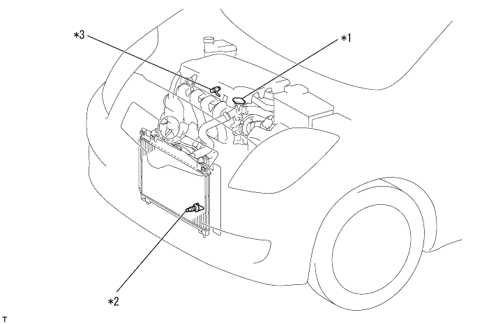
- To avoid the danger of being burned, do not remove the radiator cap sub-assembly while the engine and radiator assembly are still hot. Thermal expansion will cause hot engine coolant and steam to blow out from the radiator assembly.
Loosen the radiator drain cock plug.
Remove the radiator cap sub-assembly.
Loosen the cylinder block drain cock plug, then drain the coolant.
*1
| Water Filler Cap Sub-assembly
| *2
| Radiator Drain Cock Plug
|
*3
| Cylinder Block Drain Cock Plug
| -
| -
|
| 7. DRAIN AUTOMATIC TRANSAXLE FLUID (for Automatic Transaxle) |
Remove the drain plug and gasket, and drain the ATF.
Install a new gasket and the drain plug.
- Torque:
- 49 N*m{500 kgf*cm, 36 ft.*lbf}
| 8. DRAIN MANUAL TRANSAXLE OIL (for Manual Transaxle) |
Remove the filler plug and the gasket.
Remove the drain plug and the gasket, and then drain the manual transaxle oil.
Install a new gasket and the drain plug.
- Torque:
- 39 N*m{400 kgf*cm, 29 ft.*lbf}
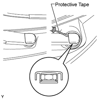
| 9. REMOVE FRONT WIPER ARM HEAD CAP |
Using a screwdriver with its tip wrapped in protective tape, disengage the claw and remove the 2 front wiper arm head caps.
| 10. REMOVE FRONT WIPER ARM AND BLADE
ASSEMBLY LH |
Operate the wiper, then stop the windshield wiper motor in the automatic stop position.
Remove the nut and front wiper arm.
| 11. REMOVE FRONT WIPER ARM AND BLADE
ASSEMBLY RH |
- HINT:
- Use the same procedure as for the LH side.
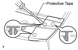
| 12. REMOVE COWL SIDE VENTILATOR SUB-ASSEMBLY LH |
Using a screwdriver with its tip wrapped in protective tape, disengage the 3 claws and remove the cowl side ventilator sub-assembly LH.
| 13. REMOVE COWL SIDE VENTILATOR SUB-ASSEMBLY RH |
- HINT:
- Use the same procedure as for the LH side.
| 14. REMOVE COWL TOP VENTILATOR LOUVER SUB-ASSEMBLY |
Disengage the 3 clips, the 4 claws and the 8 hooks.
Remove the cowl top ventilator louver sub-assembly.
Disconnect the washer hoses.
Disengage the 5 hooks.
| 15. REMOVE FRONT WIPER MOTOR AND LINK |
Remove the 2 bolts.
Slide the wiper link. Disengage the meshing of the rubber pin, then disconnect the connector and remove the front wiper motor and link.
| 16. REMOVE FRONT AIR SHUTTER SEAL RH |
Disengage the 3 claws and remove the front air shutter seal RH.
| 17. REMOVE COWL TOP PANEL OUTER |
Disengage the wire harness clamp.
Remove the 2 bolts and remove the cowl top to cowl inner brace.
Remove the 8 bolts and remove the cowl top panel outer.
| 18. REMOVE AIR CLEANER ASSEMBLY |
Separate the intake air flow meter connector and the wire harness clamp.
Separate the fuel vapor feed hose from the vacuum switching valve assembly and air cleaner hose.
Separate the vacuum switching valve connector and the wire harness clamp.
Separate the ventilation hose from the air cleaner hose.
Release the air cleaner cap sub-assembly with No. 1 air cleaner hose.
Loosen the air cleaner hose clamp on the throttle body side and remove the air cleaner cap and the air cleaner hose.
Remove the air cleaner element.
Separate the wire harness clamp from the air cleaner case.
Remove the 2 bolts and remove the air cleaner case with No. 1 air cleaner inlet.
| 19. REMOVE FUEL VAPOR FEED HOSE ASSEMBLY |
Loosen the 2 clips and remove the fuel vapor feed hose assembly from the cylinder head cover and purge pipe.
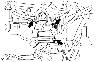
| 20. REMOVE AIR CLEANER BRACKET |
Separate the wire harness clamp from the air cleaner bracket.
Remove the 2 bolts and remove the air cleaner bracket.
| 21. REMOVE BATTERY CARRIER |
Separate the wire harness clamp from the battery carrier.
Remove the 5 bolts and remove the battery carrier.
| 22. DISCONNECT NO. 3 RADIATOR HOSE |
Disconnect No. 3 radiator hose from the water filler.
| 23. DISCONNECT RADIATOR RESERVOIR TANK HOSE |
Disconnect the radiator reservoir tank hose from the water filler.
| 24. DISCONNECT NO. 2 RADIATOR HOSE |
Disconnect No. 2 radiator hose from the water inlet.
| 25. DISCONNECT OIL COOLER OUTLET HOSE (for Automatic Transaxle) |
Loosen the clip and disconnect the oil cooler outlet hose.
| 26. DISCONNECT OIL COOLER INLET HOSE (for Automatic Transaxle) |
Loosen the clip and disconnect the oil cooler inlet hose.
| 27. REMOVE NO. 2 CYLINDER HEAD COVER |
Remove the 4 nuts and cylinder head cover No. 2.
| 28. SEPARATE TRANSMISSION CONTROL CABLE ASSEMBLY (for Automatic Transaxle) |
Remove the nut and disconnect the control cable from the control shaft lever.
Remove the clip and disconnect the control cable from the control cable bracket.
| 29. SEPARATE TRANSMISSION CONTROL CABLE ASSEMBLY (for Manual Transaxle) |
Remove the 2 clips and the 2 washers, and disconnect the 2 cables from the transaxle.
Remove the 2 clips and disconnect the 2 cables from the control cable bracket.
| 30. DISCONNECT UNION TO CHECK VALVE HOSE |
Disconnect the union to check valve hose from the booster vacuum tube.
| 31. DISCONNECT HEATER WATER OUTLET HOSE A |
Disconnect heater water outlet hose A from the heater unit.
| 32. DISCONNECT HEATER WATER HOSE INLET A |
Disconnect heater water inlet hose A from the heater unit.
| 33. DISCONNECT FUEL TUBE SUB-ASSEMBLY |
Remove No. 1 fuel pipe clamp.
Pinch the retainer as illustrated, then pull the fuel tube connector out of the pipe.
- NOTICE:
- Remove any dirt and foreign matter from the fuel tube connector before performing this work.
- Do not allow any scratches or foreign matter on the parts when disconnecting, as the fuel tube connector has the O-rings that seal the pipe.
- Perform this work by hand. Do not use any tools.
- Do not forcibly bend, twist or turn the nylon tube.
- Protect the disconnected parts by covering them with vinyl bags after disconnecting the fuel tube.
- If the fuel tube connector and pipe are stuck, push and pull to release them.
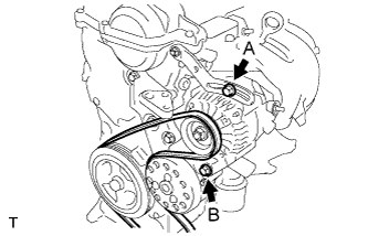
| 34. REMOVE FAN AND GENERATOR V BELT |
Loosen bolts A and B.
Release the fan and generator V belt tension and remove the fan and generator V belt.
| 35. SEPARATE COMPRESSOR ASSEMBLY WITH PULLEY (w/ Air Conditioning System) |
Disconnect the connector.
Remove the 4 bolts and separate the with pulley compressor assembly.
- HINT:
- Remove the compressor assembly together with the low and high pressure hoses, then suspend them from the body with a piece of rope.
| 36. SEPARATE CLUTCH RELEASE CYLINDER ASSEMBLY (for Manual Transaxle) |
Remove the 4 bolts, then separate the clutch release cylinder.
- HINT:
- Suspend the clutch release cylinder with a piece of rope so as not to overload the clutch pipe.
| 37. DISCONNECT ENGINE WIRE |
Pull up the lever and disconnect the connector of the engine control computer.
Remove the 2 connectors and the clamp from the engine room junction block and disconnect the wire harness.
Remove the bolt and separate the earth wire of the engine room wire harness.
Disconnect all the wire harnesses and connectors. Make sure that no wire harness is connected between the body and engine.
| 38. REMOVE COLUMN HOLE COVER SILENCER SHEET |
Fold back the floor carpet, and then remove the 2 clips and column hole cover silencer sheet.
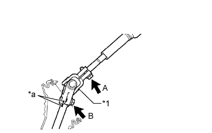
| 39. SEPARATE STEERING SLIDING YOKE SUB-ASSEMBLY |
Place matchmarks on the steering sliding yoke sub-assembly and the steering gear assembly.
Text in Illustration*1
| Steering Sliding Yoke Sub-assembly
|
*a
| Matchmark
|
Loosen bolt A, remove bolt B and separate the steering sliding yoke sub-assembly from the steering gear assembly.
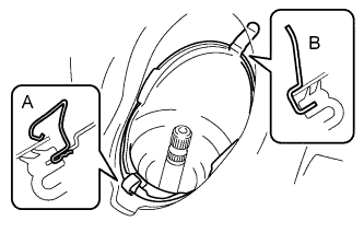
| 40. REMOVE NO. 1 STEERING COLUMN HOLE COVER SUB-ASSEMBLY |
Remove clip A, separate clip B from the body and separate the No. 1 steering column hole cover sub-assembly.
- NOTICE:
- Do not damage clip B.
| 41. REMOVE EXHAUST PIPE ASSEMBLY FRONT |
(YARIS_NCP93 RM000001J8701EX.html)
| 42. REMOVE FRONT DRIVE SHAFT ASSEMBLY |
(YARIS_NCP93 RM000001HAY02TX.html)
| 43. REMOVE FLYWHEEL HOUSING UNDER COVER (for Automatic Transaxle) |
| 44. REMOVE DRIVE PLATE AND TORQUE CONVERTER CLUTCH SETTING BOLT (for Automatic Transaxle) |
Remove the 6 torque converter set bolts.
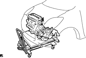
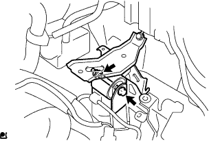
| 45. REMOVE ENGINE ASSEMBLY WITH TRANSAXLE |
Set the engine lifter.
Remove the 5 bolts and the nut and remove the engine mounting insulator RH.
Remove the through bolt and the nut and separate the engine mounting insulator LH.
Remove the 6 bolts, and remove the engine assembly with transaxle and the front suspension crossmember from the vehicle.
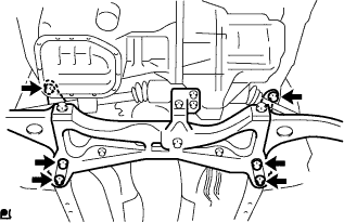
| 46. REMOVE FRONT SUSPENSION CROSSMEMBER SUB-ASSEMBLY |
Remove the bolt and remove the radio setting condenser.
Remove the bolt and remove the oxygen sensor wiring bracket.
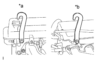
Install the engine hangers with the bolts, as shown in the illustration.
Text in Illustration*a
| Front
|
*b
| rear
|
- Torque:
- 40 N*m{408 kgf*cm, 30 ft.*lbf}
- HINT:
Part Name
| Part Number
|
Engine Hanger
| 12281-21010
|
Bolt
| 91642-81025
|
Using an engine sling device and a chain block, suspend the engine assembly with transaxle and front suspension crossmember.
Remove the through bolt from the engine moving control rod and remove the front suspension crossmember.
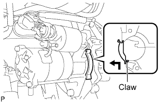
| 47. REMOVE FLYWHEEL HOUSING SIDE COVER |
Disengage the claw while pushing it upward and remove the flywheel housing side cover.
| 48. REMOVE STARTER ASSEMBLY |
Remove the terminal cap.
Remove the nut and remove terminal 30.
Disconnect the connector.
Remove the 2 bolts and remove the starter assembly.
| 49. REMOVE AUTOMATIC TRANSAXLE ASSEMBLY (for Automatic Transaxle) |
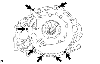
Remove the 7 bolts and remove the automatic transaxle with torque converter.
| 50. REMOVE DRIVE PLATE AND RING GEAR SUB-ASSEMBLY (for Automatic Transaxle) |
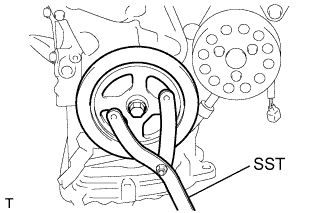
Hold the crankshaft with SST.
- SST
- 09960-10010(09962-01000,09963-01000)
Remove the 6 bolts, rear drive plate spacer, drive plate and ring gear sub-assembly, and front drive plate spacer.
| 51. REMOVE CONTROL CABLE BRACKET (for Manual Transaxle) |
Remove the 2 bolts and the control cable bracket.
| 52. REMOVE MANUAL TRANSAXLE ASSEMBLY (for Manual Transaxle) |
Remove the 7 bolts and the manual transaxle.
| 53. REMOVE CLUTCH COVER ASSEMBLY (for Manual Transaxle) |
Align the matchmark on the clutch cover assembly with the one on the flywheel.
Text in Illustration*a
| matchmarks
|
Loosen each set bolt one turn at a time until the spring tension is released.
Remove the set bolts and pull off the clutch cover.
- NOTICE:
- Do not drop the clutch disc.
| 54. REMOVE CLUTCH DISC ASSEMBLY (for Manual Transaxle) |
| 55. REMOVE FLYWHEEL SUB-ASSEMBLY (for Manual Transaxle) |
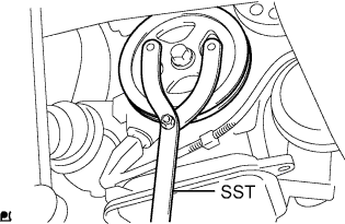
Hold the crankshaft with SST.
- SST
- 09960-10010(09962-01000,09963-01000)
Remove the 6 bolts and flywheel.
Disconnect all the sensor connectors and wire harness clamps from the engine assembly and remove the engine wire harness.
| 57. REMOVE DRIVE SHAFT HEAT INSULATOR SUB-ASSEMBLY |
Remove the bolt and nut and remove the drive shaft heat insulator.
| 58. REMOVE ENGINE MOUNTING INSULATOR LH |
- HINT:
- Only perform this procedure when replacement of the engine mounting insulator LH is necessary.
Remove the 5 bolts and engine mounting insulator LH.