Water Pump (For Sedan) -- Installation |
| 1. INSTALL ENGINE WATER PUMP ASSEMBLY |
Install the engine water pump assembly through a new gasket with the 3 bolts and 2 nuts.
- Torque:
- 11 N*m{112 kgf*cm, 8.1 ft.*lbf}
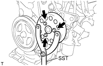
| 2. INSTALL WATER PUMP PULLEY |
Provisionally install the water pump pulley with the 3 bolts.
Using SST, hold the engine water pump pulley.
- SST
- 09960-10010(09962-01000,09963-00700)
 |
Tighten the 3 bolts to the specified torque.
- Torque:
- 15 N*m{153 kgf*cm, 11 ft.*lbf}
| 3. INSTALL ENGINE MOUNTING INSULATOR SUB-ASSEMBLY RH |
Install the engine mounting insulator sub-assembly RH with the 5 bolts and nut.
- Torque:
- 52 N*m{530 kgf*cm, 38 ft.*lbf}
 |
| 4. INSTALL GENERATOR ASSEMBLY |
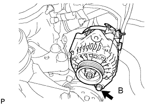 |
Provisionally install the generator with fixing bolt B.
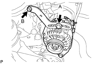
Provisionally install the fan belt adjusting slider with fan belt adjusting slider fixing bolts A and B, then move the generator toward the cylinder block and tighten bolt B.
- Torque:
- 11 N*m{112 kgf*cm, 8.1 ft.*lbf}
 |
Install the connector and the wire harness clamp.
 |
Install terminal B with the nut.
- Torque:
- 9.8 N*m{100 kgf*cm, 7.2 ft.*lbf}
Install the terminal cap.
| 5. INSTALL FAN & GENERATOR V BELT |
Provisionally install the fan and generator V belt onto each pulley.
- NOTICE:
- Make sure that there is no foreign matter or liquid, such as oil, on the belt and pulleys.
- Make sure that the V belt is securely fitted into the rib grooves of the pulley.
| 6. ADJUST FAN & GENERATOR V BELT |
Insert an adjusting bar between the engine mounting bracket and generator assembly. Pull the adjusting bar toward the vehicle front to adjust the generator V belt tension (YARIS_NCP93 RM000001DCH00ZX_01_0001.html).
Text in Illustration *a OK *b NG - NOTICE:
- Do not insert the adjusting bar between the camshaft timing oil control valve assembly and generator assembly. It could damage the camshaft timing oil control valve assembly.
 |
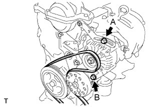
First tighten bolt A, then tighten bolt B.
- Torque:
- 19 N*m{189 kgf*cm, 14 ft.*lbf} for bolt A
- 54 N*m{551 kgf*cm, 40 ft.*lbf} for bolt B
 |
| 7. INSPECT FAN & GENERATOR V BELT |
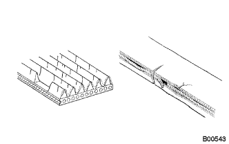 |
Check the belt for wear, cracks or other signs of damage.
If any of the following defects is found, replace the V-ribbed belt.- HINT:
- The belt is cracked.
- The belt is worn out to the extent that the wires are exposed.
- The belt has chunks missing from the ribbed groves.
Check that the belt fits properly in the ribbed grooves.
Text in Illustration *a CORRECT *b INCORRECT - HINT:
- Check with your hand, to confirm that the belt has not slipped out of the grooves on the bottom to the pulley. If it has slipped out, replace the V-ribbed belt. Install a new V-ribbed belt correctly.
 |
Inspect the V belt deflection and tension.
Text in Illustration *A w/o Air Conditioner *B w/ Air Conditioner - Deflection:
Item Specified Condition New belt 8.0 to 9.0 mm (0.31 to 0.35 in) Used belt 12.5 to 13.5 mm (0.49 to 0.53 in)
- Tension:
Item Specified Condition New belt 700 to 800 N (71 to 82 kg, 157 to 180 lb) Used belt 300 to 400 N (31 to 41 kg, 67 to 90 lb)
- HINT:
- When inspecting the V belt deflection, apply 98 N (10 kgf) tensile force to it.
- Perform the V belt inspection and adjustment while the engine is cold.
- V-ribbed belt tension and deflection should be checked immediately after installation of a new belt, and after cranking the engine when inspecting a used belt.
- Check the V belt deflection at the point between the specified pulleys where the deflection is greatest.
- When installing a new belt, set its tension to the intermediate value of the specification.
- When inspecting a belt which has been used for over 5 minutes, apply the Used Belt specifications.
- When reinstalling a belt which has been used for over 5 minutes, adjust its deflection and tension to the intermediate values of each Used Belt specification.
- V-ribbed belt tension and deflection should be checked after 2 revolutions of engine cranking.
- When using a belt tension gauge, confirm its accuracy by using a master gauge first.
 |
| 8. CONNECT CABLE TO NEGATIVE BATTERY TERMINAL |
- Torque:
- 5.4 N*m{55 kgf*cm, 48 in.*lbf}
| 9. ADD ENGINE COOLANT |
Tighten all the plugs.
Pour engine coolant into the radiator assembly until it overflows.
- Capacity:
- M/T 4.8 liters (5.1 USqts, 4.5 lmp. qts)
- A/T 4.7 liters (5.0 USqts, 4.4 lmp. qts)
- NOTICE:
- Do not substitute water for engine coolant.
- HINT:
- Use of improper engine coolant may damage the engine coolant system.
- Use only Toyota Super Long Life Coolant or similar high quality ethylene glycol based non-silicate, non-amine, non-nitrite, and non-borate engine coolant with long-life hybrid organic acid technology (coolant with long-life hybrid organic acid technology consists of a combination of low phosphates and organic acids).
Check the engine coolant level inside the radiator assembly by squeezing the inlet and outlet radiator hoses several times by hand. If the engine coolant level goes down, add engine coolant.
Install the radiator cap sub-assembly securely.
Slowly pour engine coolant into the radiator reservoir until it reaches the FULL line.
Bleed air from the cooling system.
Warm up the engine until the thermostat opens. While the thermostat is open, circulate the coolant for several minutes.
- HINT:
- The thermostat open timing can be confirmed by pressing the No. 2 radiator hose by hand, and checking when when the coolant starts to flow inside the hose.
Maintain the engine speed at 2,000 to 2,500 rpm and warm up the engine until the cooling fan operates.
Press the No. 2 radiator hose and No. 3 radiator hose several times by hand to bleed air.
- NOTICE:
- When pressing the radiator houses
- Wear protective glove.
- Be careful as the radiator hoses are hot.
- Keep your hands away form the radiator fan.
Stop the engine and wait until the coolant cools down.
If the engine coolant level is below the full level, perform steps (b) through (g) again and repeat the operation until the engine coolant level stays at the full level.
Recheck the engine coolant level inside the radiator reservoir tank assembly. If it is below the full level, add engine coolant.
| 10. CHECK FOR ENGINE COOLANT LEAKAGE |
- CAUTION:
- To avoid the danger of being burned, do not remove the water filler cap sub-assembly while the engine and radiator assembly are still hot. Thermal expansion will cause hot engine coolant and steam to blow out from the radiator assembly.
Fill the radiator assembly with engine coolant, and attach a radiator cap tester.
 |
Pump the tester to 118 kPa (1.2 kgf/cm2, 17.1 psi), and then check that the pressure does not drop.
If the pressure drops, check the hoses, radiator assembly and water pump assembly for leaks. If there are no signs or traces of external engine coolant leaks, check the heater core, cylinder block and head.
| 11. INSTALL ENGINE UNDER COVER RH |