Meter / Gauge System (For Sedan) Fuel Gauge Malfunction
DESCRIPTION
WIRING DIAGRAM
INSPECTION PROCEDURE
PERFORM ACTIVE TEST USING TECHSTREAM (FUEL GAUGE)
READ VALUE USING TECHSTREAM (FUEL GAUGE)
CHECK COMBINATION METER ASSEMBLY
INSPECT FUEL SENDER GAUGE ASSEMBLY
CHECK WIRE HARNESS AND CONNECTOR (COMBINATION METER ASSEMBLY - FUEL SENDER GAUGE ASSEMBLY)
METER / GAUGE SYSTEM (for Sedan) - Fuel Gauge Malfunction |
DESCRIPTION
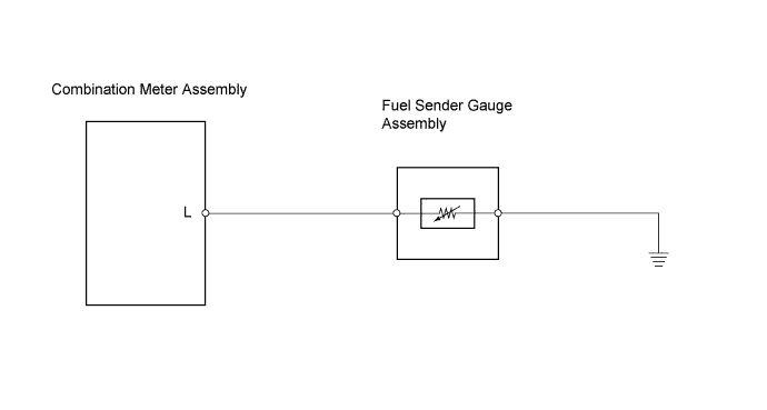
The combination meter assembly controls the fuel receiver gauge in accordance with the resistance of the fuel sender gauge that varies depending on the fuel remaining amount in the fuel tank.
WIRING DIAGRAM
INSPECTION PROCEDURE
| 1.PERFORM ACTIVE TEST USING TECHSTREAM (FUEL GAUGE) |
Connect the Techstream to the DLC3.
Turn the ignition switch ON and turn the tester ON.
Enter the following menus: Body Electrical / Combination Meter / Active Test.
- Body Electrical / Combination Meter / Active Test::
Tester Display
| Test Part
| Control Range
| Diagnostic Note
|
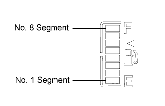
Fuel Meter Operation
| Fuel gauge
| EMPTY: Segment No.1 flashes.
1/2: Segments No.1 to 4 illuminates.
FULL: Segments No.1 to 8 illuminates.
| -
|
- OK:
- Fuel receiver gauge segments are illuminated in accordance with the tester instructions.
| 2.READ VALUE USING TECHSTREAM (FUEL GAUGE) |
Connect the Techstream to the DLC3.
Turn the ignition switch ON and turn the tester ON
Select the item below from the Data List, and read the value displayed on the Techstream.
- Body Electrical / Combination Meter / Data List::
Tester Display
| Measurement Item/Range
| Normal Condition
| Diagnostic Note
|
Fuel Input(A/D)
| Fuel input signal /
Min.: 0
Max.: 255
| Fuel receiver gauge segments
No.1 to No.8 illuminate:
14 to 34
No.1 to (No.6, No.7) illuminate:
77 to 109
No.1 to (No.4, No.5) illuminate:
135 to 172
No.1 to No.2 illuminate:
175 to 188
No.1 flashes:
194 to 200
| -
|
- OK:
- Fuel input signal displayed on the tester is approximately the same as indication.
| | REPAIR OR REPLACE HARNESS OR CONNECTOR |
|
|
| 3.CHECK COMBINATION METER ASSEMBLY |
Disconnect the J5 fuel sender gauge assembly connector.
Remove the combination meter assembly with its connectors connected.
Measure the voltage.
- Standard voltage:
Tester Connection
| Condition
| Specified Condition
|
D1-3 (L) - Body ground
| Ignition switch ON
| 11 to 14V
|
Reconnect the fuel sender gauge assembly connector.
Reinstall the combination meter assembly.
| | REPAIR OR REPLACE HARNESS OR CONNECTOR |
|
|
| 4.INSPECT FUEL SENDER GAUGE ASSEMBLY |
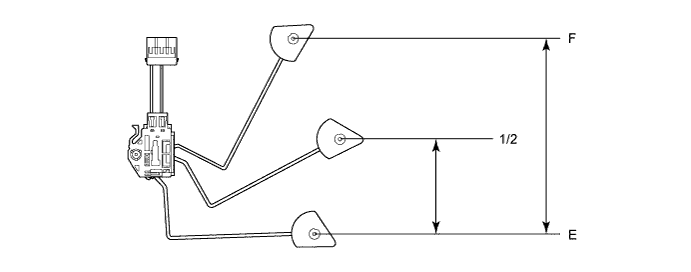
Remove the fuel sender gauge assembly.
Check that the float position is between E and F.
Measure the resistance between terminals 2 and 1 of the fuel sender gauge connector.
- Standard resistance:
Float Level
| Float Position (mm (in.))
| Specified Condition
|
F
| 146.2 (5.76) to 158.2 (6.23)
| 13.5 Ω to 16.5 Ω
|
1/2
| 76.4 (3.01) to 88.4 (3.48)
| 195.3 Ω to 221.3 Ω
|
E
| 0 (0)
| 405.5 Ω to 414.5 Ω
|
Reinstall the fuel sender gauge assembly.
| 5.CHECK WIRE HARNESS AND CONNECTOR (COMBINATION METER ASSEMBLY - FUEL SENDER GAUGE ASSEMBLY) |
Disconnect the D1 combination meter assembly connector.
Disconnect the J5 fuel sender gauge assembly connector.
Measure the resistance.
- Standard resistance:
Tester Connection
| Specified Condition
|
D1-3 (L) - J5-2
| Below 1Ω
|
J5-3 - Body ground
| Below 1Ω
|
Reconnect the combination meter assembly and fuel sender gauge assembly connectors.
| | REPAIR OR REPLACE HARNESS OR CONNECTOR |
|
|