Air Conditioning System (For Sedan) Blower Motor Circuit
DESCRIPTION
WIRING DIAGRAM
INSPECTION PROCEDURE
INSPECT FUSE (GAUGE, HTR)
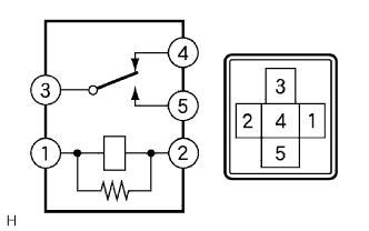
INSPECT HTR RELAY
INSPECT BLOWER MOTOR
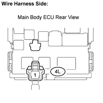
CHECK HARNESS AND CONNECTOR (HTR FUSE - MAIN BODY ECU)
CHECK MAIN BODY ECU
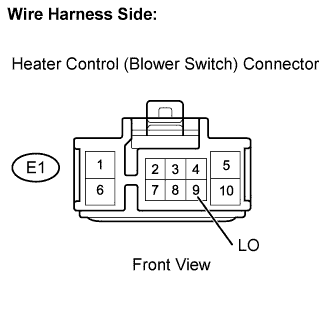
CHECK HARNESS AND CONNECTOR (MAIN BODY ECU - HEATER CONTROL (BLOWER SWITCH))
CHECK HARNESS AND CONNECTOR (MAIN BODY ECU - BLOWER MOTOR)
CHECK HARNESS AND CONNECTOR (BLOWER RESISTOR - BLOWER MOTOR)
INSPECT BLOWER RESISTOR
INSPECT HEATER CONTROL (BLOWER SWITCH)
CHECK HARNESS AND CONNECTOR (HEATER CONTROL (BLOWER SWITCH) - BLOWER RESISTOR)
AIR CONDITIONING SYSTEM (for Sedan) - Blower Motor Circuit |
DESCRIPTION
When the heater control (blower switch) is set to position 1 or higher, the contact of the HTR relay is closed, current flows to the blower motor, and the blower motor operates. The blower motor speed can be changed by exchanging the ground and the blower resistor circuit with the heater control (blower switch).
WIRING DIAGRAM
INSPECTION PROCEDURE
| 1.INSPECT FUSE (GAUGE, HTR) |
Remove the GAUGE fuse from the main body ECU.
Remove the HTR fuse from the engine room relay block.
Measure the resistance.
- Standard resistance:
Tester Item
| Specified Condition
|
GAUGE fuse
| Below 1 Ω
|
HTR fuse
| Below 1 Ω
|
Reinstall the GAUGE fuse.
Reinstall the HTR fuse.
Remove the HTR relay from the main body ECU.
Measure the resistance.
- Standard resistance:
Tester Connection
| Specified Condition
|
3 - 4
| Below 1 Ω
|
3 - 5
| 10 kΩ or higher
|
3 - 4
| 10 kΩ or higher
(when battery voltage is applied to terminals 1 and 2)
|
3 - 5
| Below 1 Ω
(when battery voltage is applied to terminals 1 and 2)
|
Reinstall the HTR relay.
Disconnect the E4 blower motor connector.
Connect the positive (+) lead from the battery to terminal 2 and the negative (-) lead to terminal 1, then check that the blower motor operates smoothly.
- OK:
- The blower motor operates smoothly.
Measure the current.
- Standard current:
Tester Connection
| Specified Condition
|
E4-2 (+B) - E4-1 (GND)
| 1 to 3 A
|
Reconnect the blower motor connector.
| 4.CHECK HARNESS AND CONNECTOR (HTR FUSE - MAIN BODY ECU) |
Disconnect the 4L main body ECU connector.
Measure the voltage.
- Standard voltage:
Tester Connection
| Condition
| Specified Condition
|
4L-1 - Body ground
| Always
| 11 to 14 V
|
Reconnect the main body ECU connector.
| | REPAIR OR REPLACE HARNESS OR CONNECTOR |
|
|
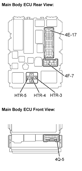
Remove the HTR relay from the main body ECU.
Measure the resistance.
- Standard resistance:
Tester Connection
| Specified Condition
|
4F-7 - HTR-3
| Below 1 Ω
|
4E-17 - HTR-4
| Below 1 Ω
|
Measure the voltage.
- Standard voltage:
Tester Connection
| Condition
| Specified Condition
|
HTR-5 - Body ground
| Always
| 11 to 14 V
|
Reinstall the HTR relay.
Measure the voltage.
- Standard voltage:
Tester Connection
| Condition
| Specified Condition
|
4Q-5 - Body ground
| Ignition switch ON
| 11 to 14 V
|
| 6.CHECK HARNESS AND CONNECTOR (MAIN BODY ECU - HEATER CONTROL (BLOWER SWITCH)) |
Disconnect the E1 heater control (blower switch) connector.
Measure the voltage.
- Standard voltage:
Tester Connection
| Condition
| Specified Condition
|
E1-9 (LO) - Body ground
| Ignition switch ON
| 11 to 14 V
|
Reconnect the heater control (blower switch) connector.
| | REPAIR OR REPLACE HARNESS OR CONNECTOR |
|
|
| 7.CHECK HARNESS AND CONNECTOR (MAIN BODY ECU - BLOWER MOTOR) |
Disconnect the E4 blower motor connector.
Measure the voltage.
- Standard voltage:
Tester Connection
| Condition
| Specified Condition
|
E4-1 (+B) - Body ground
| Ignition switch ON
| 11 to 14 V
|
Reconnect the blower motor connector.
| | REPAIR OR REPLACE HARNESS OR CONNECTOR |
|
|
| 8.CHECK HARNESS AND CONNECTOR (BLOWER RESISTOR - BLOWER MOTOR) |
Disconnect the E3 blower resistor connector.
Disconnect the E4 blower motor connector.
Measure the resistance.
- Standard resistance:
Tester Connection
| Specified Condition
|
E3-4 - E4-1
| Below 1 Ω
|
Reconnect the blower resistor connector.
Reconnect the blower motor connector.
| | REPAIR OR REPLACE HARNESS OR CONNECTOR |
|
|
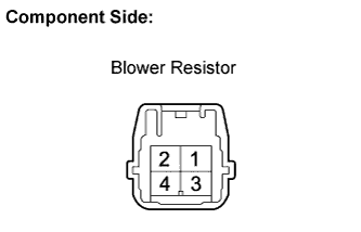
| 9.INSPECT BLOWER RESISTOR |
Remove the blower resistor.
Measure the resistance.
- Standard resistance:
Tester Connection
| Specified Condition
|
4 - 1
| 3.12 to 3.60Ω
|
4 - 3
| 1.45 to 1.67Ω
|
4 - 2
| 0.52 to 0.60Ω
|
Reinstall the blower resistor.
| 10.INSPECT HEATER CONTROL (BLOWER SWITCH) |
Remove the heater control (blower switch).
Measure the resistance.
- Standard resistance:
Switch Position
| Tester Connection
| Specified Condition
|
0
| ALL - 5 (E)
| 10 kΩ or higher
|
1
| 9 (LO) - 5 (E)
| Below 1 Ω
|
1 - 2
| 9 (LO) - 5 (E) - 7 (M1)
| Below 1 Ω
|
2
| 9 (LO) - 5 (E) - 7 (M1)
| Below 1 Ω
|
2 - 3
| 9 (LO) - 5 (E) - 7 (M1) - 6 (M2)
| Below 1 Ω
|
3
| 9 (LO) - 5 (E) - 6 (M2)
| Below 1 Ω
|
3 - 4
| 9 (LO) - 5 (E) - 6 (M2) - 10 (HI)
| Below 1 Ω
|
4
| 9 (LO) - 5 (E) - 10 (HI)
| Below 1 Ω
|
Reinstall the heater control (blower switch).
| 11.CHECK HARNESS AND CONNECTOR (HEATER CONTROL (BLOWER SWITCH) - BLOWER RESISTOR) |
Disconnect the E1 heater control (blower switch) connector.
Disconnect the E3 blower resistor connector.
Measure the resistance.
- Standard resistance:
Tester Connection
| Specified Condition
|
E1-5 (E) - E3-1
| Below 1 Ω
|
E1-6 (M2) - E3-2
| Below 1 Ω
|
E1-7 (M1) - E3-3
| Below 1 Ω
|
E1-10 (HI) - E3-4
| Below 1 Ω
|
Reconnect the heater control (blower switch) connector.
Reconnect the blower resistor connector.
| | REPAIR OR REPLACE HARNESS OR CONNECTOR |
|
|
| OK |
|
|
|
| REPAIR OR REPLACE HARNESS OR CONNECTOR (BLOWER RESISTOR - BODY GROUND) |
|