Dtc B1650/32 Occupant Classification System Malfunction
DESCRIPTION
WIRING DIAGRAM
INSPECTION PROCEDURE
CHECK DTC (CENTER AIRBAG SENSOR ASSEMBLY)
CHECK DTC (OCCUPANT CLASSIFICATION ECU)
CHECK CONNECTION OF CONNECTORS
CHECK FLOOR WIRE (FOR OPEN)
CHECK FLOOR WIRE (FOR SHORT)
CHECK FLOOR WIRE (TO B+)
CHECK FLOOR WIRE (TO GROUND)
CHECK CENTER AIRBAG SENSOR ASSEMBLY
REPLACE OCCUPANT CLASSIFICATION ECU
PERFORM ZERO POINT CALIBRATION
PERFORM SENSITIVITY CHECK
DTC B1650/32 Occupant Classification System Malfunction |
DESCRIPTION
The occupant classification system circuit consists of the center airbag sensor assembly and the occupant classification system.When the center airbag sensor assembly receives signals from the occupant classification ECU, it determines whether or not the front passenger airbag, front seat side airbag assembly RH and seat belt pretensioner RH should be operated.DTC B1650/32 is set when a malfunction is detected in the occupant classification system circuit.DTC No.
| DTC Detecting Conditions
| Trouble Areas
|
B1650/32
| - Occupant classification system malfunction
- Center airbag sensor assembly detects line short circuit signal, open circuit signal, short circuit to ground signal or short circuit to B+ signal in occupant classification system circuit for 2 seconds
- Center airbag sensor assembly malfunction
| - Floor wire
- Occupant classification system
- Center airbag sensor assembly
|
WIRING DIAGRAM
INSPECTION PROCEDURE
- NOTICE:
- In order to prevent unexpected airbag deployment, disconnect the following connectors before inspecting parts such as wire harnesses, if the application of tester probes to the center airbag sensor assembly connector is necessary.
- Turn the ignition switch to the lock position.
- Disconnect the negative (-) terminal cable from the battery, and wait for at least 90 seconds.
- Disconnect the connector from the center airbag sensor assembly.
- Disconnect the connectors from the steering pad.
- Disconnect the connectors from the front passenger airbag assembly.
- Disconnect the connector from the front seat outer belt assembly LH.
- Disconnect the connector from the front seat outer belt assembly RH.
- HINT:
- Skip the following steps if side and curtain shield airbags are not fitted.
- Disconnect the connector from the front seat side airbag assembly LH.
- Disconnect the connector from the front seat side airbag assembly RH.
- Disconnect the connector from the curtain shield airbag assembly LH.
- Disconnect the connector from the curtain shield airbag assembly RH.
| 1.CHECK DTC (CENTER AIRBAG SENSOR ASSEMBLY) |
Turn the ignition switch to the on position, and wait for at least 60 seconds.
Clear the DTCs stored in the memory (YARIS_NCP93 RM000000XFE0D2X.html).
Turn the ignition switch to the lock position.
Turn the ignition switch to the on position, and wait for at least 60 seconds.
Check for DTCs (YARIS_NCP93 RM000000XFE0D2X.html).
- OK:
- DTC B1650/32 is not output.
- HINT:
- DTCs other than B1650/32 may be output at this time, but they are not related to this check.
| | USE SIMULATION METHOD TO CHECK |
|
|
| 2.CHECK DTC (OCCUPANT CLASSIFICATION ECU) |
Turn the ignition switch to the on position, and wait for at least 10 seconds.
Using the Techstream, check for DTCs of the occupant classification ECU (YARIS_NCP93 RM0000010VK06DX.html).
- OK:
- DTC is not output.
| 3.CHECK CONNECTION OF CONNECTORS |
Turn the ignition switch to the lock position.
Disconnect the negative (-) terminal cable from the battery, and wait for at least 90 seconds.
Check that the connectors are properly connected to the center airbag sensor assembly and the occupant classification ECU.
- OK:
- The connectors are properly connected.
| 4.CHECK FLOOR WIRE (FOR OPEN) |
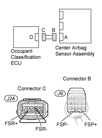
Disconnect the connectors from the center airbag sensor assembly and the occupant classification ECU.
Using a service wire, connect J24-8 (FSR+) and J24-4 (FSR-) of connector C.
- NOTICE:
- Do not forcibly insert the service wire into the terminals of the connector when connecting.
Measure the resistance.
- Standard resistance:
Tester Connection
| Condition
| Specified Condition
|
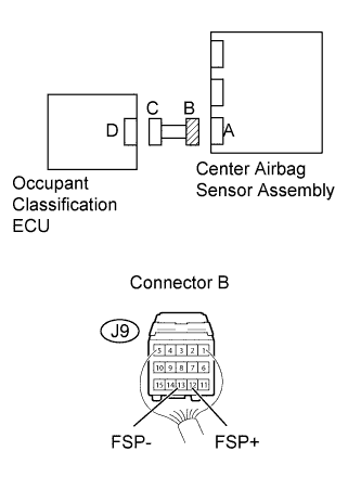
J9-12 (FSP+) - J9-13 (FSP-)
| Always
| Below 1 Ω
|
| | REPAIR OR REPLACE FLOOR WIRE |
|
|
| 5.CHECK FLOOR WIRE (FOR SHORT) |
Disconnect the service wire from connector C.
Measure the resistance.
- Standard resistance:
Tester Connection
| Condition
| Specified Condition
|
J9-12 (FSP+) - J9-13 (FSP-)
| Always
| 1 MΩ or Higher
|
| | REPAIR OR REPLACE FLOOR WIRE |
|
|
| 6.CHECK FLOOR WIRE (TO B+) |
Connect the negative (-) terminal cable to the battery, and wait for at least 2 seconds.
Turn the ignition switch to the on position.
Measure the voltage.
- Standard voltage:
Tester Connection
| Switch Condition
| Specified Condition
|
J9-12 (FSP+) - Body ground
| Ignition switch ON
| Below 1 V
|
J9-13 (FSP-) - Body ground
| Ignition switch ON
| Below 1 V
|
| | REPAIR OR REPLACE FLOOR WIRE |
|
|
| 7.CHECK FLOOR WIRE (TO GROUND) |
Turn the ignition switch to the lock position.
Disconnect the negative (-) terminal cable from the battery, and wait for at least 90 seconds.
Measure the resistance.
- Standard resistance:
Tester Connection
| Condition
| Specified Condition
|
J9-12 (FSP+) - Body ground
| Always
| 1 MΩ or Higher
|
J9-13 (FSP-) - Body ground
| Always
| 1 MΩ or Higher
|
| | REPAIR OR REPLACE FLOOR WIRE |
|
|
| 8.CHECK CENTER AIRBAG SENSOR ASSEMBLY |
Turn the ignition switch to the lock position.
Disconnect the negative (-) terminal cable from the battery, and wait for at least 90 seconds.
Replace the center airbag sensor assembly (YARIS_NCP93 RM000000V6U021X.html).
- HINT:
- Perform the inspection using parts from a normal vehicle when possible.
Connect the connectors to the center airbag sensor assembly.
Connect the negative (-) terminal cable to the battery, and wait for at least 2 seconds.
Turn the ignition switch to the on position, and wait for at least 60 seconds.
Clear the DTCs stored in the memory (YARIS_NCP93 RM000000XFE0D2X.html).
Turn the ignition switch to the lock position.
Turn the ignition switch to the on position, and wait for at least 60 seconds.
Check for DTCs (YARIS_NCP93 RM000000XFE0D2X.html).
- OK:
- DTC B1650/32 is not output.
- HINT:
- DTCs other than B1650/32 may be output at this time, but they are not related to this check.
| | USE SIMULATION METHOD TO CHECK |
|
|
| 9.REPLACE OCCUPANT CLASSIFICATION ECU |
Turn the ignition switch to the lock position.
Disconnect the negative (-) terminal cable from the battery, and wait for at least 90 seconds.
Replace the occupant classification ECU (YARIS_NCP93 RM0000012DU00KX.html).
| 10.PERFORM ZERO POINT CALIBRATION |
Connect the negative (-) terminal cable to the battery.
Connect the Techstream to the DLC3.
Turn the ignition switch to the on position.
Using the Techstream, perform the zero point calibration (YARIS_NCP93 RM0000010VN06EX.html).
- OK:
- COMPLETED is displayed on the tester.
| 11.PERFORM SENSITIVITY CHECK |
Using the Techstream, perform the sensitivity check (YARIS_NCP93 RM0000010VN06EX.html).
Confirm that nothing is placed on the passenger seat.
Confirm that the first sensor reading is within the standard range.
- Standard range:
- -3.2 to 3.2 kg (-7 to 7 lb)
Place a 30 kg (66.14 lb) weight (e.g. a lead mass) onto the front passenger seat.
Confirm that the sensitivity is within the standard range.
- Standard range:
- 27 to 33 kg (59.52 to 72.75 lb)
- HINT:
- When performing the sensitivity check, use a solid metal weight (the check result may not be accurate if a liquid weight is used).