Automatic Transaxle Assembly (For Hatchback) Removal
DRAIN AUTOMATIC TRANSAXLE FLUID
REMOVE REAR CONSOLE BOX ASSEMBLY
REMOVE BATTERY
REMOVE BATTERY TRAY
REMOVE BATTERY CARRIER
REMOVE AIR CLEANER ASSEMBLY
REMOVE AIR CLEANER BRACKET
REMOVE STARTER ASSEMBLY (for Cold Area Specification Vehicles)
REMOVE STARTER ASSEMBLY (except Cold Area Specification Vehicles)
SEPARATE TRANSMISSION CONTROL CABLE ASSEMBLY
SEPARATE WIRE HARNESS
DISCONNECT INLET OIL COOLER HOSE
DISCONNECT OUTLET OIL COOLER HOSE
REMOVE FRONT DRIVE SHAFT ASSEMBLIES
REMOVE FRONT SUSPENSION CROSSMEMBER SUB-ASSEMBLY
SUPPORT ENGINE ASSEMBLY
REMOVE ENGINE MOVING CONTROL ROD BRACKET
REMOVE ENGINE MOUNTING BRACKET LH
REMOVE FLYWHEEL HOUSING UNDER COVER
REMOVE TORQUE CONVERTER SETTING BOLT
REMOVE AUTOMATIC TRANSAXLE ASSEMBLY
REMOVE TORQUE CONVERTER ASSEMBLY
REMOVE SPEEDOMETER DRIVEN HOLE COVER SUB-ASSEMBLY
REMOVE NO. 1 TRANSMISSION CONTROL CABLE BRACKET
DISCONNECT INLET NO. 1 OIL COOLER TUBE
DISCONNECT OUTLET NO. 1 OIL COOLER TUBE
REMOVE NO. 2 OIL COOLER TUBE CLAMP
REMOVE TRANSMISSION OIL LEVEL DIPSTICK SUB-ASSEMBLY
REMOVE TRANSMISSION OIL FILLER TUBE SUB-ASSEMBLY
REMOVE WIRE HARNESS CLAMP BRACKET
Automatic Transaxle Assembly (For Hatchback) -- Removal |
| 1. DRAIN AUTOMATIC TRANSAXLE FLUID |
Remove the drain plug and gasket, and drain ATF.
Install a new gasket and the drain plug.
- Torque:
- 49 N*m{500 kgf*cm, 36 ft.*lbf}
| 2. REMOVE REAR CONSOLE BOX ASSEMBLY |
(YARIS_NCP93 RM000003726005X.html)
Disconnect the cable from the battery terminal.
Loosen the 2 nuts and remove the battery clamp.
Remove the battery.
| 5. REMOVE BATTERY CARRIER |
Disengage the 6 clamps and disconnect the wire harness from the battery carrier.
Remove the 5 bolts and the battery carrier.
| 6. REMOVE AIR CLEANER ASSEMBLY |
Disengage the clamp and disconnect the fuel vapor feed hose assembly from the No. 1 air cleaner hose.
Loosen the 2 hose clamps and disconnect the fuel vapor feed hose assembly from the No. 1 air cleaner hose and vacuum switching valve assembly.
Disconnect the No. 2 fuel vapor feed hose from the intake manifold.
Disengage the 2 clamps and disconnect the wire harness from the air cleaner cap sub-assembly and vacuum switching valve assembly.
Disconnect the mass air flow meter connector.
Disconnect the vacuum switching valve connector.
Loosen the hose clamp and disconnect the No. 1 air cleaner hose from the throttle with motor body assembly.
Disengage the 2 clamps and remove the air cleaner cap sub-assembly with No. 1 air cleaner hose.
Remove the air cleaner element.
Disengage the clamp and disconnect the wire harness from the air cleaner case.
Remove the 2 bolts and the air cleaner case from the air cleaner bracket.
| 7. REMOVE AIR CLEANER BRACKET |
Disengage the clamp and disconnect the wire harness from the air cleaner bracket.
Remove the 2 bolts and the air cleaner bracket.
| 8. REMOVE STARTER ASSEMBLY (for Cold Area Specification Vehicles) |
(YARIS_NCP93 RM0000034TC00YX.html)
| 9. REMOVE STARTER ASSEMBLY (except Cold Area Specification Vehicles) |
(YARIS_NCP93 RM000001E2703AX.html)
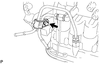
| 10. SEPARATE TRANSMISSION CONTROL CABLE ASSEMBLY |
Remove the nut and disconnect the transmission control cable assembly from the control shaft lever.
Remove the clip and separate the transmission control cable assembly from the No. 1 transmission control cable bracket.
| 11. SEPARATE WIRE HARNESS |
Remove the bolt and separate the No. 3 engine wire from the automatic transaxle assembly.
Disconnect the park/neutral position switch connector.
Disconnect the transmission wire connector.
Disconnect the transmission revolution sensor connector.
Disengage the 7 clamps and separate the wire harness.
| 12. DISCONNECT INLET OIL COOLER HOSE |
Loosen the hose clamp and disconnect the oil cooler inlet hose.
| 13. DISCONNECT OUTLET OIL COOLER HOSE |
Loosen the hose clamp and disconnect the oil cooler outlet hose.
| 14. REMOVE FRONT DRIVE SHAFT ASSEMBLIES |
(YARIS_NCP93 RM000000UBO017X.html)
| 15. REMOVE FRONT SUSPENSION CROSSMEMBER SUB-ASSEMBLY |
(YARIS_NCP93 RM000000UNK03LX.html)
| 16. SUPPORT ENGINE ASSEMBLY |
Place the wooden blocks or plate lift attachments in the positions shown in the illustration and set an engine lifter underneath the engine assembly.
Text in Illustration
| Attachment Placement Positions
|
- NOTICE:
- Place the wooden blocks or plate lift attachments so that the engine assembly with transaxle is level.
- As the engine assembly with transaxle is very heavy, be sure to support it securely.
- To prevent deformation of the oil pan, never set any attachments against the oil pan of the engine assembly.
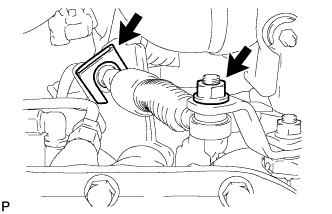
| 17. REMOVE ENGINE MOVING CONTROL ROD BRACKET |
Remove the 3 bolts and the engine moving control rod bracket.
| 18. REMOVE ENGINE MOUNTING BRACKET LH |
Remove the bolt and nut, and separate the engine mounting insulator LH from the engine mounting bracket LH.
Remove the 4 bolts and the engine mounting bracket LH from the automatic transaxle assembly.
| 19. REMOVE FLYWHEEL HOUSING UNDER COVER |
Remove the flywheel housing under cover.
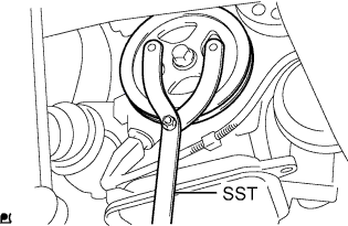
| 20. REMOVE TORQUE CONVERTER SETTING BOLT |
Use SST to hold the crankshaft pulley in place.
- SST
- 09960-10010(09962-01000,09963-01000)
Remove the 6 torque converter setting bolts.
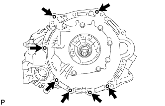
| 21. REMOVE AUTOMATIC TRANSAXLE ASSEMBLY |
On a flat location, set the attachment in the positions shown in the illustration, and set the automatic transaxle assembly.
Text in Illustration
| Attachment Placement Positions
|
- NOTICE:
- To prevent deformation of the oil pan, never set any attachments against the oil pan of the automatic transaxle assembly.
Remove the 7 bolts and remove the automatic transaxle assembly from the engine assembly.
- NOTICE:
- To prevent damage to the knock pins, do not pry between the transaxle and engine.
| 22. REMOVE TORQUE CONVERTER ASSEMBLY |
Remove the torque converter assembly from the automatic transaxle assembly.
- NOTICE:
- Remove the torque converter assembly from the input shaft horizontally.
| 23. REMOVE SPEEDOMETER DRIVEN HOLE COVER SUB-ASSEMBLY |
Remove the bolt and the speedometer driven hole cover sub-assembly from the automatic transaxle assembly.
Remove the O-ring from the speedometer driven hole cover.
| 24. REMOVE NO. 1 TRANSMISSION CONTROL CABLE BRACKET |
Remove the 2 bolts and the No. 1 transmission control cable bracket from the automatic transaxle assembly.
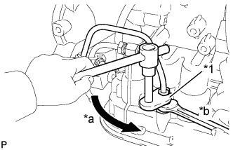
| 25. DISCONNECT INLET NO. 1 OIL COOLER TUBE |
Using a union nut wrench 14 mm, disconnect the inlet No. 1 oil cooler tube while holding the oil cooler tube union with a wrench.
Text in Illustration*1
| Union Nut Wrench 14 mm
|
*a
| Turn
|
*b
| Hold
|
| 26. DISCONNECT OUTLET NO. 1 OIL COOLER TUBE |
Using a union nut wrench 14 mm, disconnect the outlet No. 1 oil cooler tube while holding the oil cooler tube union with a wrench.
Text in Illustration*1
| Union Nut Wrench 14 mm
|
*a
| Turn
|
*b
| Hold
|
| 27. REMOVE NO. 2 OIL COOLER TUBE CLAMP |
Remove the bolt and the No. 2 oil cooler tube clamp from the transmission oil filler tube sub-assembly.
Remove the inlet No. 1 oil cooler tube and the outlet No. 1 oil cooler tube from the automatic transaxle assembly.
| 28. REMOVE TRANSMISSION OIL LEVEL DIPSTICK SUB-ASSEMBLY |
Remove the transmission oil level dipstick sub-assembly from the transmission oil filler tube sub-assembly.
| 29. REMOVE TRANSMISSION OIL FILLER TUBE SUB-ASSEMBLY |
Disconnect the breather hose from the transmission oil filler tube sub-assembly.
Remove the bolt and the transmission oil filler tube sub-assembly from the automatic transaxle assembly.
Remove the O-ring from the transmission oil filler tube sub-assembly.
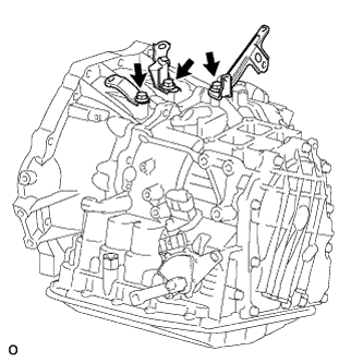
| 30. REMOVE WIRE HARNESS CLAMP BRACKET |
Remove the 3 bolts and the 3 wire harness clamp brackets from the automatic transaxle assembly.