Dtc B2780 Push Switch / Key Unlock Warning Switch Malfunction
DESCRIPTION
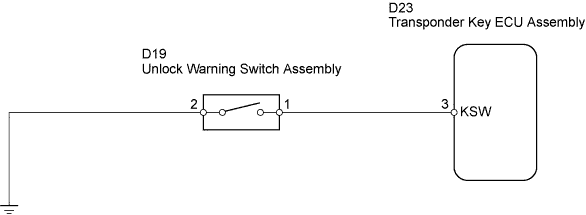
WIRING DIAGRAM
INSPECTION PROCEDURE
READ VALUE USING TECHSTREAM
INSPECT UNLOCK WARNING SWITCH ASSEMBLY
CHECK HARNESS AND CONNECTOR (UNLOCK WARNING SWITCH ASSEMBLY - BODY GROUND)
CHECK HARNESS AND CONNECTOR (TRANSPONDER KEY ECU - UNLOCK WARNING SWITCH ASSEMBLY)
DTC B2780 Push Switch / Key Unlock Warning Switch Malfunction |
DESCRIPTION
This DTC will be output if the transponder key ECU does not detect that the unlock warning switch is ON even when the ignition switch is ON. Under normal conditions, the unlock warning switch is ON when the ignition switch is ON.DTC No.
| DTC Detection Condition
| Trouble Area
|
B2780
| Unlock warning switch ON is not detected when ignition switch is ON
| - Unlock warning switch assembly
- Wire harness
- Transponder key ECU assembly
|
WIRING DIAGRAM
INSPECTION PROCEDURE
| 1.READ VALUE USING TECHSTREAM |
Connect a Techstream to the DLC3.
Turn the ignition switch to ON.
Turn the tester on.
Enter the following menus: Body Electrical / Immobiliser / Data List.
According to the display on tester, read the "Data List".
Immobiliser: Tester Display
| Measurement Item/Range
| Normal Condition
| Diagnostic Note
|
Key SW
| Unlock warning switch signal/
ON or OFF
| OFF: No key is in ignition key cylinder
ON: Key is in ignition key cylinder
| -
|
- OK:
- "ON" (key is in ignition key cylinder) appears on the screen.
| 2.INSPECT UNLOCK WARNING SWITCH ASSEMBLY |
Remove the unlock warning switch assembly.
Measure the resistance of the switch.
- Standard resistance:
Tester Connection
| Switch Condition
| Specified Condition
|
1 - 2
| Pushed
| Below 1 Ω
|
1 - 2
| Not pushed
| 10 kΩ or higher
|
Reinstall the unlock warning switch assembly.
| 3.CHECK HARNESS AND CONNECTOR (UNLOCK WARNING SWITCH ASSEMBLY - BODY GROUND) |
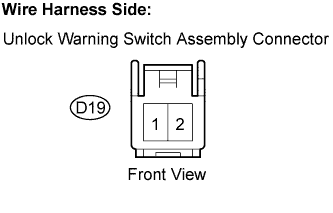
Disconnect the D19 Unlock warning switch assembly connector.
Measure the resistance of the wire harness side connector.
- Standard resistance:
Tester Connection
| Specified Condition
|
D19-2 - Body ground
| Below 1 Ω
|
Reconnect the D19 unlock warning switch assembly connector.
| | REPAIR OR REPLACE HARNESS OR CONNECTOR |
|
|
| 4.CHECK HARNESS AND CONNECTOR (TRANSPONDER KEY ECU - UNLOCK WARNING SWITCH ASSEMBLY) |
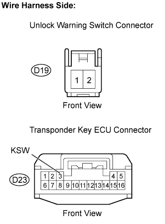
Disconnect the D23 transponder key ECU connector.
Disconnect the D19 unlock warning switch assembly connector.
Measure the resistance of the wire harness side connectors.
- Standard resistance:
Tester Connection
| Specified Condition
|
D23-3 (KSW) - D19-1
| Below 1 Ω
|
Reconnect the D23 transponder key ECU connector.
Reconnect the D19 unlock warning switch assembly connector.
| | REPAIR OR REPLACE HARNESS OR CONNECTOR |
|
|