Engine Immobiliser System (For Sedan) Ecu Power Source Circuit
DESCRIPTION
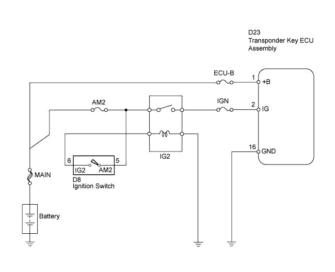
WIRING DIAGRAM
INSPECTION PROCEDURE
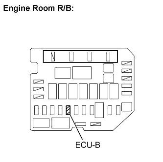
INSPECT FUSE (ECU-B)
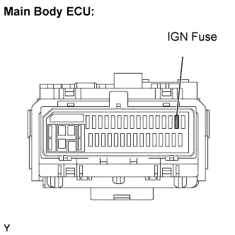
INSPECT FUSE (IGN)
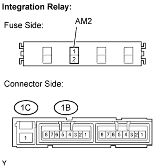
INSPECT INTEGRATION NO.1 RELAY (IG2 RELAY AND AM2 FUSE)
INSPECT IGNITION SWITCH ASSEMBLY
CHECK HARNESS AND CONNECTOR (TRANSPONDER KEY ECU - BATTERY AND BODY GROUND)
ENGINE IMMOBILISER SYSTEM (for Sedan) - ECU Power Source Circuit |
DESCRIPTION
This circuit provides power to operate the transponder key ECU assembly.
WIRING DIAGRAM
INSPECTION PROCEDURE
Remove the ECU-B fuse from the engine room R/B and J/B.
Measure the ECU-B fuse resistance.
- Standard resistance:
- Below 1 Ω
Reinstall the ECU-B fuse.
Remove the IGN fuse from the main body ECU.
Measure the IGN fuse resistance.
- Standard resistance:
- Below 1 Ω
Reinstall the IGN fuse.
| 3.INSPECT INTEGRATION NO.1 RELAY (IG2 RELAY AND AM2 FUSE) |
Remove the integration relay from the engine room R/B and J/B.
Inspect the AM2 fuse.
Remove the AM2 fuse from the integration relay.
Measure the resistance of the AM2 fuse.
- Standard resistance:
- Below 1 Ω
Reinstall the AM2 fuse.
Inspect the IG2 relay.
Measure the resistance between the terminals shown below.
- Standard resistance:
Tester Connections
| Specified Conditions
|
1C-1-1B-4
| 10 kΩ or higher
|
Below 1 Ω (when battery voltage is applied to terminals 1B-2 and 1B-3)
|
1C-1-1B-1
| Below 1 Ω
|
Reinstall the integration relay.
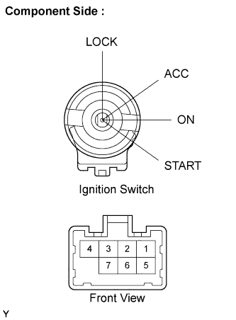
| 4.INSPECT IGNITION SWITCH ASSEMBLY |
Disconnect the D8 ignition switch connector.
Measure the resistance between the terminals shown below.
- Standard resistance:
Key Position
| Tester Connection
| Specified Condition
|
LOCK
| -
| 10 kΩor higher
|
ACC
| 2-4
| Below 1 Ω
|
ON
| 1-2-4
| Below 1 Ω
|
5-6
| Below 1 Ω
|
START
| 1-3-4
| Below 1 Ω
|
5-6-7
| Below 1 Ω
|
Reconnect the D8 ignition switch connector.
| 5.CHECK HARNESS AND CONNECTOR (TRANSPONDER KEY ECU - BATTERY AND BODY GROUND) |
Disconnect the D23 transponder key ECU connector.
Measure the voltage of the wire harness side connector.
- Standard voltage:
Tester Connection
| Condition
| Specified Condition
|
D23-1 (+B) - Body ground
| D23-1 (+B) - Body ground
| 11 to 14 V
|
D23-2 (IG) - Body ground
| Ignition switch OFF
| Below 1 V
|
Ignition switch ON
| 11 to 14 V
|
Measure the resistance of the wire harness side connector.
- Standard resistance:
Tester Connection
| Specified Condition
|
D23-16 (GND) - Body ground
| Below 1 Ω
|
Reconnect the D23 transponder key ECU connector.
| | REPAIR OR REPLACE HARNESS OR CONNECTOR |
|
|