DESCRIPTION
WIRING DIAGRAM
INSPECTION PROCEDURE
INSPECT FRONT DOOR LOCK ASSEMBLY LH
CHECK HARNESS AND CONNECTOR (MAIN BODY ECU - FRONT DOOR LOCK ASSEMBLY LH)
CHECK DOOR LOCK OPERATION
INSPECT DOOR CONTROL SWITCH (for Front Driver Door Side)
CHECK HARNESS AND CONNECTOR (MAIN BODY ECU - DOOR CONTROL SWITCH (Front Driver Door Side))
READ VALUE USING TECHSTREAM
CHECK HARNESS AND CONNECTOR (DRIVER SIDE DOOR LOCK ASSEMBLY - MAIN BODY ECU)
READ VALUE USING TECHSTREAM
CHECK HARNESS AND CONNECTOR (PASSENGER SIDE DOOR LOCK ASSEMBLY - MAIN BODY ECU)
INSPECT DOOR CONTROL SWITCH (for Front Passenger Door Side)
CHECK HARNESS AND CONNECTOR (MAIN BODY ECU - DOOR CONTROL SWITCH (Passenger Door Side))
POWER DOOR LOCK CONTROL SYSTEM (for Sedan) - All Doors cannot be Locked / Unlocked Simultaneously |
DESCRIPTION
The main body ECU receives switch signals from the door control switch and driver side door key cylinder, and activates the door lock motor on each door accordingly.
WIRING DIAGRAM
INSPECTION PROCEDURE
| 1.INSPECT FRONT DOOR LOCK ASSEMBLY LH |
Apply the battery voltage to the door lock motor and measure the resistance.
- Standard resistance:
Tester Connection
| Condition
| Specified Condition
|
8 (LSSR) - 7 (E)
| Battery positive (+) → Terminal 1
Battery negative(-) → Terminal 4
| Below 1 Ω
|
8 (LSSR) - 7 (E)
| Battery positive (+) → Terminal 4
Battery negative(-) → Terminal 1
| 10 kΩ or higher
|
| 2.CHECK HARNESS AND CONNECTOR (MAIN BODY ECU - FRONT DOOR LOCK ASSEMBLY LH) |
Disconnect the D33main body ECU connector.
Disconnect the G5 door lock connector.
Measure the resistance.
- Standard resistance:
Tester Connection
| Specified Condition
|
D33-21 (LSWD) - G5-8 (LSSR)
| Below 1 Ω
|
D33-21 (LSWD) or G5-8 (LSSR) - Body ground
| 10 kΩ or higher
|
Reconnect the main body ECU connector.
Reconnect the door lock connector.
| | REPAIR OR REPLACE HARNESS OR CONNECTOR |
|
|
| 3.CHECK DOOR LOCK OPERATION |
Proceed to the next step according to the symptom listed in the table below.
- Result:
Symptom
| Proceed to
|
Doors cannot be locked using door control switch (for front driver door side)
| A
|
Doors cannot be locked using driver side door key cylinder
| B
|
Doors cannot be locked using front passenger side door key cylinder
| C
|
Doors cannot be locked using door control switch (for passenger side)
| D
|
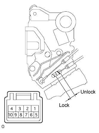
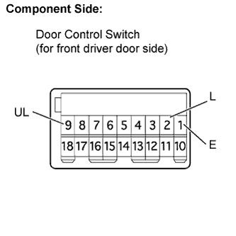
| 4.INSPECT DOOR CONTROL SWITCH (for Front Driver Door Side) |
w/ Power window:
Disconnect the G1 door control switch (for front driver door side) connector.
Measure the resistance of the switch.
- Standard resistance:
Tester Connection
| Switch Condition
| Specified Condition
|
2 (L) - 1 (E)
| Lock
| Below 1 Ω
|
9 (UL) - 1 (E)
| Unlock
| Below 1 Ω
|
2 (L) - 1 (E)
| OFF
| 10 kΩ or higher
|
9 (UL) - 1 (E)
| OFF
| 10 kΩ or higher
|
Reconnect the door control switch (for front driver door side) connector.
w/o Power window:
Disconnect the G7 door control switch (for front driver door side) connector.
Measure the resistance of the switch.
- Standard resistance:
Tester Connection
| Switch Condition
| Specified Condition
|
3 (L) - 4 (E)
| Lock
| Below 1 Ω
|
2 (UL) - 4 (E)
| Unlock
| Below 1 Ω
|
3 (L) - 4 (E)
| OFF
| 10 kΩ or higher
|
2 (UL) - 4 (E)
| OFF
| 10 kΩ or higher
|
Reconnect the door control switch (for front driver door side) connector.
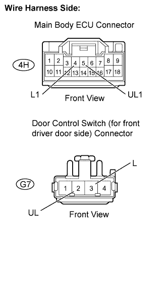
| 5.CHECK HARNESS AND CONNECTOR (MAIN BODY ECU - DOOR CONTROL SWITCH (Front Driver Door Side)) |
w/ Power window:
Disconnect the 4H main body ECU connector.
Disconnect the G1 door control switch (for front driver door side) connector.
Measure the resistance.
- Standard resistance:
Tester Connection
| Specified Condition
|
4H-5(UL1) - G1-9(UL)
| Below 1 Ω
|
4H-4(L1) - G1-2(L)
| Below 1 Ω
|
4H-5(UL1) or G1-9(UL) - Body ground
| 10 kΩ or higher
|
4H-4(L1) or G1-2(L) - Body ground
| 10 kΩ or higher
|
Reconnect the main body ECU connector.
Reconnect the door control switch (for front driver door side) connector.
w/o Power window:
Disconnect the 4H main body ECU connector.
Disconnect the G7 door control switch (for front driver door side) connector.
Measure the resistance.
- Standard resistance:
Tester Connection
| Specified Condition
|
4H-5 (UL1) - G7-2 (UL)
| Below 1 Ω
|
4H-4 (L1) - G7-3 (L)
| Below 1 Ω
|
4H-5 (UL1) or G7-2 (UL) - Body ground
| 10 kΩ or higher
|
4H-4 (L1) or G7-3 (L) - Body ground
| 10 kΩ or higher
|
Reconnect the main body ECU connector.
Reconnect the door control switch (for front driver door side) connector.
| | REPAIR OR REPLACE HARNESS OR CONNECTOR |
|
|
| 6.READ VALUE USING TECHSTREAM |
Connect a Techstream to the DLC3.
Turn the ignition switch ON.
Turn the tester on.
Enter the following menus: Body Electrical / Main Body / Data List.
According to the display on tester, read on the "Data List".
- Main Body:
Tester Display
| Measurement Item/Range
| Normal Condition
| Diagnostic Note
|
Door Key SW-Lock
| Door key-linked lock switch signal/ ON or OFF
| ON: Door key cylinder is turned to lock position
OFF: Driver side door key cylinder is turned to unlock position
| -
|
- Main Body:
Tester Display
| Measurement Item/Range
| Normal Condition
| Diagnostic Note
|
Door Key SW-Unlock
| Door key-linked lock switch signal/ ON or OFF
| ON: Door key cylinder is turned to lock position
OFF: Driver side door key cylinder is turned to unlock position
| -
|
- OK:
- ON (driver side door key cylinder is turned to lock/unlock position) appears on tester screen.
| 7.CHECK HARNESS AND CONNECTOR (DRIVER SIDE DOOR LOCK ASSEMBLY - MAIN BODY ECU) |
Disconnect the D33 and 4H main body ECU connectors.
Disconnect the G5 door lock connector.
Measure the resistance.
- Standard resistance:
Tester Connection
| Specified Condition
|
D33-14 (UL3) - G5-10 (UL)
| Below 1 Ω
|
4H-7 (L2) - G5-9 (L)
| Below 1 Ω
|
D33-14 (UL3) or G5-10 (UL) - Body ground
| 10 kΩ or higher
|
4H-7 (L2) or G5-9 (L) - Body ground
| 10 kΩ or higher
|
Reconnect the main body ECU connectors.
Reconnect the door lock connector.
| | REPAIR OR REPLACE HARNESS OR CONNECTOR |
|
|
| 8.READ VALUE USING TECHSTREAM |
Connect a Techstream to the DLC3.
Turn the ignition switch to ON.
Turn the tester on.
Enter the following menus: Body Electrical / Main Body / Data List.
According to the display on tester, read on the "Data List".
- Main Body:
Tester Display
| Measurement Item/Range
| Normal Condition
| Diagnostic Note
|
Door Key SW-Lock
| Door key-linked lock switch signal/ ON or OFF
| ON: Door key cylinder is turned to lock position
OFF: Driver side door key cylinder is turned to unlock position
| -
|
- Main Body:
Tester Display
| Measurement Item/Range
| Normal Condition
| Diagnostic Note
|
D Door Key SW-UL
| Door key-linked unlock switch signal/ ON or OFF
| ON: Door key cylinder is turned to unlock position
OFF: Door key cylinder is turned to lock position
| -
|
- OK:
- ON (driver side door key cylinder is turned to lock/unlock position) appears on screen.
| 9.CHECK HARNESS AND CONNECTOR (PASSENGER SIDE DOOR LOCK ASSEMBLY - MAIN BODY ECU) |
Disconnect the 4H main body ECU connector.
Disconnect the F5 front door lock assembly connector.
Measure the resistance.
- Standard resistance:
Tester Connection
| Specified Condition
|
4H-15 (UL2) - F5-5 (UL)
| Below 1 Ω
|
4H-16 (L2) - F5-6 (L)
| Below 1 Ω
|
4H-15 (UL2) or F5-5 (UL) - Body ground
| 10 kΩ or higher
|
4H-16 (L2) or F5-6 (L) - Body ground
| 10 kΩ or higher
|
Reconnect the main body ECU connector.
Reconnect the front door lock assembly connector.
| | REPAIR OR REPLACE HARNESS OR CONNECTOR |
|
|
| 10.INSPECT DOOR CONTROL SWITCH (for Front Passenger Door Side) |
Disconnect the F7 door control switch (for front passenger door side) connector.
Measure the resistance of the switch.
- Standard resistance:
Tester Connection
| Switch Condition
| Specified Condition
|
3 (L) - 4 (E)
| Lock
| Below 1 Ω
|
2 (UL) - 4 (E)
| Unlock
| Below 1 Ω
|
3 (L) - 4 (E)
| OFF
| 10 kΩ or higher
|
2 (UL) - 4 (E)
| OFF
| 10 kΩ or higher
|
Reconnect the door control switch (for front passenger door side) connector.
| 11.CHECK HARNESS AND CONNECTOR (MAIN BODY ECU - DOOR CONTROL SWITCH (Passenger Door Side)) |
Disconnect the 4C and 4E main body ECU connector.
Disconnect the F7 door control switch (for front passenger door side) connector.
Measure the resistance.
- Standard resistance:
Tester Connection
| Specified Condition
|
4C-10 (UL1) - F7-2 (UL)
| Below 1 Ω
|
4E-11 (L1) - F7-3 (L)
| Below 1 Ω
|
4C-10 (UL1) or F7-2 (UL) - Body ground
| 10 kΩ or higher
|
4E-11 (L1) or F7-3 (L) - Body ground
| 10 kΩ or higher
|
Reconnect the main body ECU connector.
Reconnect the door control switch (for front passenger door side) connector.
| | REPAIR OR REPLACE HARNESS OR CONNECTOR |
|
|