Audio And Visual System (For Sedan) Steering Pad Switch Circuit
DESCRIPTION
WIRING DIAGRAM
INSPECTION PROCEDURE
INSPECT RADIO RECEIVER ASSEMBLY
INSPECT STEERING PAD SWITCH ASSEMBLY
INSPECT SPIRAL CABLE SUB-ASSEMBLY
AUDIO AND VISUAL SYSTEM (for Sedan) - Steering Pad Switch Circuit |
DESCRIPTION
This circuit sends an operation signal from the steering pad switch assembly to the radio receiver assembly.If there is an open in the circuit, the radio system cannot be operated using the steering pad switch assembly.If there is a short in the circuit, the resulting condition is the same as if a switch were continuously pressed. Therefore, the radio receiver assembly cannot be operated using the steering pad switch assembly, and the radio receiver assembly itself cannot function.
WIRING DIAGRAM
INSPECTION PROCEDURE
- NOTICE:
- The vehicle is equipped with an SRS (Supplemental Restraint System). Before servicing (including removal or installation of parts), be sure to read the precaution for Supplemental Restraint System (YARIS_NCP93 RM000000KT10D1X.html).
| 1.INSPECT RADIO RECEIVER ASSEMBLY |
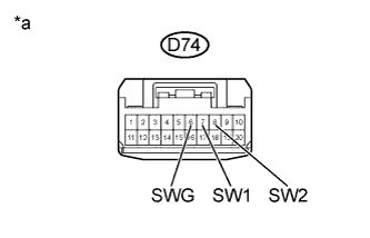
Disconnect the D74 radio receiver assembly connector.
Measure the resistance according to the value(s) in the table below.
- Standard Resistance:
Tester Connection
| Switch Condition
| Specified Condition
|
D74-7 (SW1) - D74-6 (SWG)
| No switch pushed
| 95 to 105 kΩ
|
Seek+ switch pushed
| Below 2.5 Ω
|
Seek- switch pushed
| 313 to 345 Ω
|
Volume+ switch pushed
| 950 to 1050 Ω
|
Volume- switch pushed
| 2955 to 3265 Ω
|
D74-8 (SW2) - D74-6 (SWG)
| No switch pushed
| 95 to 105 kΩ
|
MODE switch pushed
| Below 2.5 Ω
|
Text in Illustration*a
| Front view of wire harness connector
(to Radio Receiver Assembly)
|
| 2.INSPECT STEERING PAD SWITCH ASSEMBLY |
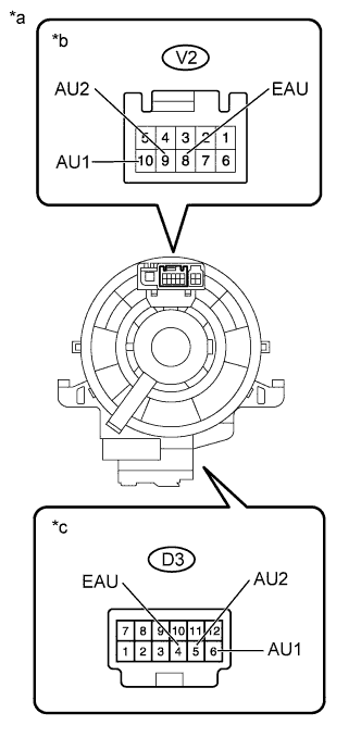
Remove the steering pad switch assembly (YARIS_NCP93 RM0000013RC00WX.html).
Text in Illustration*1
| SEEK Switch
| *2
| VOL Switch
|
*3
| MODE Switch
| -
| -
|
*a
| Component without harness connected
(Steering Pad Switch Assembly)
| -
| -
|
Measure the resistance according to the value(s) in the table below.
- Standard Resistance:
Tester Connection
| Switch Condition
| Specified Condition
|
V2-10 (AU1) - V2-8 (EAU)
| No switch pushed
| 95 to 105 kΩ
|
Seek+ switch pushed
| Below 2.5 Ω
|
Seek- switch pushed
| 313 to 345 Ω
|
Volume+ switch pushed
| 950 to 1050 Ω
|
Volume- switch pushed
| 2955 to 3265 Ω
|
V2-9 (AU2) - V2-8 (EAU)
| No switch pushed
| 95 to 105 kΩ
|
MODE switch pushed
| Below 2.5 Ω
|
| 3.INSPECT SPIRAL CABLE SUB-ASSEMBLY |
Remove the spiral cable sub-assembly (YARIS_NCP93 RM000000V6R023X.html).
Measure the resistance according to the value(s) in the table below.
- Standard Resistance:
Tester Connection
| Switch Condition
| Specified Condition
|
V2-8 (EAU) - D3-4 (EAU)
| Center
| Below 1 Ω
|
2.5 rotations to the left
| Below 1 Ω
|
2.5 rotations to the right
| Below 1 Ω
|
V2-10 (AU1) - D3-6 (AU1)
| Center
| Below 1 Ω
|
2.5 rotations to the left
| Below 1 Ω
|
2.5 rotations to the right
| Below 1 Ω
|
V2-9 (AU2) - D3-5 (AU2)
| Center
| Below 1 Ω
|
2.5 rotations to the left
| Below 1 Ω
|
2.5 rotations to the right
| Below 1 Ω
|
Text in Illustration*a
| Component without harness connected
(Spiral Cable Sub-assembly)
|
*b
| Steering Pad Switch Assembly Side
|
*c
| Vehicle Side
|
- NOTICE:
- The spiral cable sub-assembly is an important part of the SRS airbag system. Incorrect removal or installation of the spiral cable sub-assembly may prevent the airbag from deploying. Refer to the pages shown in the brackets.
- HINT:
- Removal (YARIS_NCP93 RM000000V6R023X.html)
- Installation (YARIS_NCP93 RM000000V6O023X.html)
| OK |
|
|
|
| REPAIR OR REPLACE HARNESS OR CONNECTOR (RADIO RECEIVER ASSEMBLY - SPIRAL CABLE SUB-ASSEMBLY) |
|