Dtc B1653/35 Seat Position Airbag Sensor Circuit Malfunction
DESCRIPTION
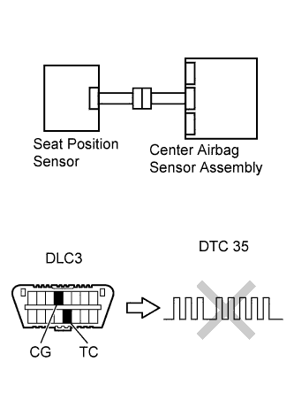
WIRING DIAGRAM
INSPECTION PROCEDURE
CHECK DTC
CHECK CONNECTION OF CONNECTORS
CHECK SEAT POSITION SENSOR CIRCUIT (FOR OPEN)
CHECK SEAT POSITION SENSOR CIRCUIT (FOR SHORT)
CHECK SEAT POSITION SENSOR CIRCUIT (TO B+)
CHECK SEAT POSITION SENSOR CIRCUIT (TO GROUND)
CHECK SEAT POSITION SENSOR
REPLACE SEAT POSITION SENSOR
CHECK CENTER AIRBAG SENSOR ASSEMBLY
CHECK FLOOR WIRE (FOR OPEN)
CHECK FLOOR WIRE (FOR SHORT)
CHECK FLOOR WIRE (TO B+)
CHECK FLOOR WIRE (TO GROUND)
DTC B1653/35 Seat Position Airbag Sensor Circuit Malfunction |
DESCRIPTION
The seat position sensor circuit consists of the center airbag sensor assembly and the seat position sensor.DTC B1653/35 is recorded when a malfunction is detected in the seat position sensor circuit.DTC No.
| DTC Detecting Condition
| Trouble Area
|
B1653/35
| - Center airbag sensor assembly detects line short circuit signal, open circuit signal, short circuit to ground signal or short circuit to B+ signal in seat position sensor circuit for 2 seconds.
- Seat position sensor malfunction
- Center airbag sensor assembly malfunction
| - Floor wire
- Front seat inner belt assembly LH
- Seat position sensor
- Center airbag sensor assembly
|
WIRING DIAGRAM
INSPECTION PROCEDURE
- NOTICE:
- In order to prevent unexpected airbag deployment, disconnect the following connectors before inspecting parts such as wire harnesses, if the application of tester probes to the center airbag sensor assembly connector is necessary.
- Turn the ignition switch to the lock position.
- Disconnect the negative (-) terminal cable from the battery, and wait for at least 90 seconds.
- Disconnect the connector from the center airbag sensor assembly.
- Disconnect the connectors from the steering pad.
- Disconnect the connectors from the front passenger airbag assembly.
- Disconnect the connector from the front seat outer belt assembly LH
- Disconnect the connector from the front seat outer belt assembly RH.
- HINT:
- Skip the following steps if side and curtain shield airbags are not fitted.
- Disconnect the connector from the front seat side airbag assembly LH.
- Disconnect the connector from the front seat side airbag assembly RH.
- Disconnect the connector from the curtain shield airbag assembly LH.
- Disconnect the connector from the curtain shield airbag assembly RH.
Turn the ignition switch on, and wait for at least 60 seconds.
Clear the DTCs stored in the memory (YARIS_NCP93 RM000000XFE0D2X.html).
Turn the ignition switch off.
Turn the ignition switch on, and wait for at least 60 seconds.
Check the DTCs (YARIS_NCP93 RM000000XFE0D2X.html).
- OK:
- DTC B1653/35 is not output.
- HINT:
- DTCs other than DTC B1653/35 may be output at this time, but they are not related to this check.
| | USE SIMULATION METHOD TO CHECK |
|
|
| 2.CHECK CONNECTION OF CONNECTORS |
Turn the ignition switch off.
Disconnect the negative (-) terminal cable from the battery, and wait for at least 90 seconds.
Check that the connectors are properly connected to the center airbag sensor assembly and the seat position sensor.
- OK:
- The connectors are properly connected.
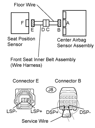
| 3.CHECK SEAT POSITION SENSOR CIRCUIT (FOR OPEN) |
Disconnect the connectors from the center airbag sensor assembly and the seat position sensor.
Using a service wire, connect J8-14 (DSP+) and J8-13 (DSP-) of connector B.
- NOTICE:
- Do not forcibly insert the service wire into the terminals of the connector when connecting.
Measure the resistance.
- Standard resistance:
Tester Connection
| Condition
| Specified Condition
|
2 (LSP+) - 1 (LSP-)
| Always
| Below 1 Ω
|
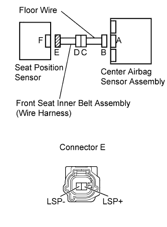
| 4.CHECK SEAT POSITION SENSOR CIRCUIT (FOR SHORT) |
Disconnect the service wire from connector B.
Measure the resistance.
- Standard resistance:
Tester Connection
| Condition
| Specified Condition
|
2 (LSP+) - 1 (LSP-)
| Always
| 1 MΩ or higher
|
| 5.CHECK SEAT POSITION SENSOR CIRCUIT (TO B+) |
Connect the negative (-) terminal cable to the battery, and wait for at least 2 seconds.
Turn the ignition switch on.
Measure the voltage.
- Standard voltage:
Tester Connection
| Switch Condition
| Specified Condition
|
2 (LSP+) - Body ground
| Ignition switch ON
| Below 1 V
|
1 (LSP-) - Body ground
| Ignition switch ON
| Below 1 V
|
| 6.CHECK SEAT POSITION SENSOR CIRCUIT (TO GROUND) |
Turn the ignition switch off.
Disconnect the negative (-) terminal cable from the battery, and wait for at least 90 seconds.
Measure the voltage.
- Standard resistance:
Tester Connection
| Condition
| Specified Condition
|
2 (LSP+) - Body ground
| Always
| 1 MΩ or Higher
|
1 (LSP-) - Body ground
| Always
| 1 MΩ or Higher
|
| 7.CHECK SEAT POSITION SENSOR |
Connect the connectors to the center airbag sensor assembly and the seat position sensor.
Connect the negative (-) terminal cable to the battery, and wait for at least 2 seconds.
Turn the ignition switch on, and wait for at least 60 seconds.
Clear the DTCs stored in the memory (YARIS_NCP93 RM000000XFE0D2X.html).
Turn the ignition switch off.
Turn the ignition switch on, and wait for at least 60 seconds.
Check the DTCs (YARIS_NCP93 RM000000XFE0D2X.html).
- OK:
- DTC B1653/35 is not output.
- HINT:
- DTCs other than DTC B1653/35 may be output at this time, but they are not related to this check.
| | USE SIMULATION METHOD TO CHECK |
|
|
| 8.REPLACE SEAT POSITION SENSOR |
Turn the ignition switch off.
Disconnect the negative (-) terminal cable from the battery, and wait for at least 90 seconds.
Replace the seat position sensor (YARIS_NCP93 RM0000012DQ00TX.html).
- HINT:
- Perform the inspection using parts from a normal vehicle if possible.
| 9.CHECK CENTER AIRBAG SENSOR ASSEMBLY |
Connect the negative (-) terminal cable to the battery, and wait for at least 2 seconds.
Turn the ignition switch on, and wait for at least 60 seconds.
Clear the DTCs stored in the memory (YARIS_NCP93 RM000000XFE0D2X.html).
Turn the ignition switch off.
Turn the ignition switch on, and wait for at least 60 seconds.
Check the DTCs (YARIS_NCP93 RM000000XFE0D2X.html).
- OK:
- DTC B1653/35 is not output.
- HINT:
- DTCs other than DTC B1653/35 may be output at this time, but they are not related to this check.
| | REPLACE CENTER AIRBAG SENSOR ASSEMBLY |
|
|
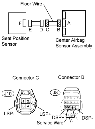
| 10.CHECK FLOOR WIRE (FOR OPEN) |
Disconnect the connectors from the center airbag sensor assembly and the seat position sensor.
Using a service wire, connect J8-14 (DSP+) and J8-13 (DSP-) of connector B.
- NOTICE:
- Do not forcibly insert the service wire into the terminals of the connector when connecting.
Measure the resistance.
- Standard resistance:
Tester Connection
| Condition
| Specified Condition
|
J10-2 (LSP+) -
J10-1 (LSP-)
| Always
| Below 1 Ω
|
| | REPAIR OR REPLACE FLOOR WIRE |
|
|
| OK |
|
|
|
| REPLACE FRONT SEAT INNER BELT ASSEMBLY LH |
|
| 11.CHECK FLOOR WIRE (FOR SHORT) |
Disconnect the service wire from connector B.
Measure the resistance.
- Standard resistance:
Tester Connection
| Condition
| Specified Condition
|
J10-2 (LSP+) -
J10-1 (LSP-)
| Always
| 1 MΩ or higher
|
| | REPAIR OR REPLACE FLOOR WIRE |
|
|
| OK |
|
|
|
| REPLACE FRONT SEAT INNER BELT ASSEMBLY LH |
|
| 12.CHECK FLOOR WIRE (TO B+) |
Connect the negative (-) terminal cable to the battery, and wait for at least 2 seconds.
Turn the ignition switch on.
Measure the voltage.
- Standard voltage:
Tester Connection
| Switch Condition
| Specified Condition
|
J10-2 (LSP+) -
Body ground
| Ignition switch ON
| Below 1 V
|
J10-1 (LSP-) -
Body ground
| Ignition switch ON
| Below 1 V
|
| | REPAIR OR REPLACE FLOOR WIRE |
|
|
| OK |
|
|
|
| REPLACE FRONT SEAT INNER BELT ASSEMBLY LH |
|
| 13.CHECK FLOOR WIRE (TO GROUND) |
Turn the ignition switch off.
Disconnect the negative (-) terminal cable from the battery, and wait for at least 90 seconds.
Measure the resistance.
- Standard resistance:
Tester Connection
| Condition
| Specified Condition
|
J10-2 (LSP+) -
Body ground
| Always
| 1 MΩ or higher
|
J10-1 (LSP-) -
Body ground
| Always
| 1 MΩ or higher
|
| | REPAIR OR REPLACE FLOOR WIRE |
|
|
| OK |
|
|
|
| REPLACE FRONT SEAT INNER BELT ASSEMBLY LH |
|