Vehicle Stability Control System (For Hatchback With Separate Type Yaw Rate Sensor) Slip Indicator Light Remains On
DESCRIPTION
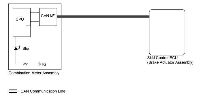
WIRING DIAGRAM
INSPECTION PROCEDURE
CHECK IF SKID CONTROL ECU CONNECTOR IS SECURELY CONNECTED
CHECK CAN COMMUNICATION SYSTEM
INSPECT BATTERY
CHECK TERMINAL VOLTAGE (IG1 TERMINAL)
CHECK HARNESS AND CONNECTOR (GND1 TERMINAL)
READ VALUE USING TECHSTREAM (SLIP INDICATOR LIGHT)
REPLACE COMBINATION METER ASSEMBLY
CHECK COMBINATION METER ASSEMBLY
VEHICLE STABILITY CONTROL SYSTEM (for Hatchback with Separate Type Yaw Rate Sensor) - Slip Indicator Light Remains ON |
DESCRIPTION
The skid control ECU (brake actuator assembly) is connected to the combination meter via CAN communication.The Slip indicator light blinks during VSC, TRAC operation.If any of the following is detected, the Slip indicator light remains on:- The skid control ECU (brake actuator assembly) connectors are disconnected from the brake actuator (skid control ECU).
- There is a malfunction in the skid control ECU (brake actuator assembly) internal circuit.
- There is an open in the harness between the combination meter and the skid control ECU (brake actuator assembly).
- The VSC, TRAC control system is defective.
- HINT:
- In same cases, the Techstream is used when the skid control ECU (brake actuator assembly) is abnormal.
WIRING DIAGRAM
INSPECTION PROCEDURE
- NOTICE:
- When replacing the brake actuator assembly, perform zero point calibration (YARIS_NCP93 RM000000XHR07EX.html).
- Inspect the fuses for circuits related to this system before performing the following inspection procedure.
| 1.CHECK IF SKID CONTROL ECU CONNECTOR IS SECURELY CONNECTED |
Check if the skid control ECU connector is securely connected.
- OK:
- The connector is securely connected.
| | CONNECT CONNECTOR TO ECU CORRECTLY |
|
|
| 2.CHECK CAN COMMUNICATION SYSTEM |
Check if CAN communication system DTCs are output (YARIS_NCP93 RM000001RSW02LX.html).
ResultResult
| Proceed to
|
DTC is not output
| A
|
DTC is output
| B
|
Check the battery voltage.
- Standard voltage:
- 11 to 14 V
| 4.CHECK TERMINAL VOLTAGE (IG1 TERMINAL) |
Disconnect the skid control ECU (brake actuator assembly) connector.
Turn the ignition switch to ON.
Measure the voltage according to the value(s) in the table below.
- Standard Voltage:
Tester Connection
| Switch Condition
| Specified Condition
|
A70-34 (IG1) - Body ground
| Ignition switch ON
| 11 to 14 V
|
Text in Illustration*a
| Front view of wire harness connector
(to Skid control ECU)
|
Turn the ignition switch off.
| | REPAIR OR REPLACE HARNESS OR CONNECTOR (IG1 CIRCUIT) |
|
|
| 5.CHECK HARNESS AND CONNECTOR (GND1 TERMINAL) |
Measure the resistance according to the value(s) in the table below.
- Standard Resistance:
Tester Connection
| Condition
| Specified Condition
|
A70-1 (GND1) - Body ground
| Always
| Below 1 Ω
|
Text in Illustration*a
| Front view of wire harness connector
(to Skid control ECU)
|
Reconnect the skid control ECU (brake actuator assembly) connector.
| | REPAIR OR REPLACE HARNESS OR CONNECTOR (GND1 CIRCUIT) |
|
|
| 6.READ VALUE USING TECHSTREAM (SLIP INDICATOR LIGHT) |
Turn the ignition switch off.
Connect the Techstream to the DLC3.
Turn the ignition switch to ON.
Turn the Techstream on.
Enter the following menus: Chassis / ABS/VSC/TRAC / Data List.
According to the display on the Techstream, read the Data List.
ABS/VSC/TRACTester Display
| Measurement Item/Range
| Normal Condition
| Diagnostic Note
|
Slip Indicator Light
| SLIP indicator light/OFF or ON
| OFF: Indicator light off
ON: Indicator light on
| -
|
When performing the Slip Indicator Light Active Test, check Slip Indicator Light in the Data List.
ABS/VSC/TRACTester Display
| Test Part
| Control Range
| Diagnostic Note
|
Slip Indicator Light
| SLIP indicator light
| Indicator light OFF/ON
| Observe combination meter [Vehicle condition] Vehicle stopped
|
ResultResult
| Proceed to
|
Data List Display
| Data List Display when Performing Active Test ON/OFF Operation
|
ON
| Changes between ON and OFF
| A
|
Does not change between ON and OFF
| B
|
OFF
| Changes between ON and OFF
| A
|
Does not change between ON and OFF
| B
|
| 7.REPLACE COMBINATION METER ASSEMBLY |
Turn the ignition switch off.
Replace the combination meter assembly (YARIS_NCP93 RM0000035EJ00BX.html).
| 8.CHECK COMBINATION METER ASSEMBLY |
Perform Active Test of the combination meter assembly using the Techstream (YARIS_NCP93 RM000001F8Q018X.html).
- OK:
- The Slip indicator light turns on or off in accordance with the Techstream.