Power Door Lock Control System (For Hatchback) All Doors Lock/Unlock Functions Do Not Operate Via Door Control Switch
DESCRIPTION
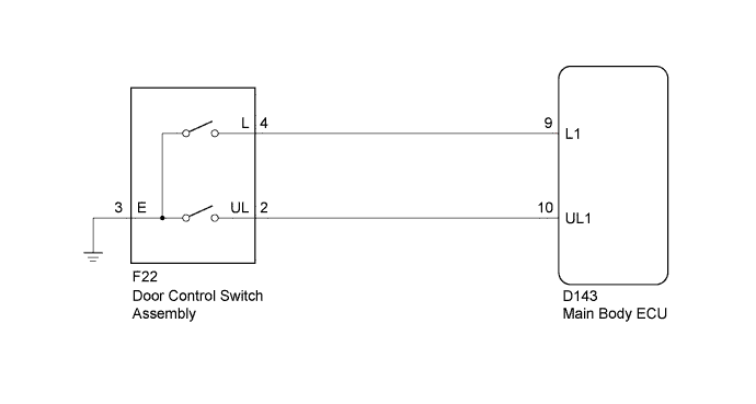
WIRING DIAGRAM
INSPECTION PROCEDURE
READ VALUE USING TECHSTREAM (DOOR CONTROL SWITCH)
INSPECT DOOR CONTROL SWITCH ASSEMBLY
CHECK HARNESS AND CONNECTOR (DOOR CONTROL SWITCH ASSEMBLY - MAIN BODY ECU AND BODY GROUND)
POWER DOOR LOCK CONTROL SYSTEM (for Hatchback) - All Doors LOCK/UNLOCK Functions do not Operate Via Door Control Switch |
DESCRIPTION
The main body ECU receives switch signals from the door control switch and activates the door lock motor on each door according to these signals.
WIRING DIAGRAM
INSPECTION PROCEDURE
| 1.READ VALUE USING TECHSTREAM (DOOR CONTROL SWITCH) |
Connect the Techstream to the DLC3.
Turn the ignition switch to ON.
Turn the Techstream on.
Enter the following menus: Body Electrical / Main Body / Data List.
According to the display on the Techstream, read the Data List.
Main BodyTester Display
| Measurement Item/Range
| Normal Condition
| Diagnostic Note
|
Door Lock SW-Lock
| Door manual lock switch signal / OFF or ON
| OFF: Door control switch is turned to unlock position
ON: Door control switch is turned to lock position
| -
|
Door Lock SW-Unlock
| Door manual unlock switch signal / OFF or ON
| OFF: Door control switch is turned to lock position
ON: Door control switch is turned to unlock position
| -
|
- OK:
- The Techstream indicates ON or OFF according to the switch operation shown in the table.
| 2.INSPECT DOOR CONTROL SWITCH ASSEMBLY |
Inspect the door control switch assembly (YARIS_NCP93 RM000004OBK005X.html).
| 3.CHECK HARNESS AND CONNECTOR (DOOR CONTROL SWITCH ASSEMBLY - MAIN BODY ECU AND BODY GROUND) |
Disconnect the F22 door control switch assembly connector.
Disconnect the D143 main body ECU connector.
Measure the resistance according to the value(s) in the table below.
- Standard Resistance:
Tester Connection
| Condition
| Specified Condition
|
F22-2 (UL) - D143-10 (UL1)
| Always
| Below 1 Ω
|
F22-4 (L) - D143-9 (L1)
| Always
| Below 1 Ω
|
F22-3 (E) - Body ground
| Always
| Below 1 Ω
|
F22-2 (UL) - Body ground
| Always
| 10 kΩ or higher
|
F22-4 (L) - Body ground
| Always
| 10 kΩ or higher
|
| | REPAIR OR REPLACE HARNESS OR CONNECTOR |
|
|