Steering Gear (For Sedan) Removal
POSITION FRONT WHEELS FACING STRAIGHT AHEAD
DISCONNECT CABLE FROM NEGATIVE BATTERY TERMINAL
REMOVE HOOD SUB-ASSEMBLY
REMOVE FRONT WIPER ARM HEAD CAP
REMOVE FRONT WIPER ARM AND BLADE ASSEMBLY LH
REMOVE FRONT WIPER ARM AND BLADE ASSEMBLY RH
REMOVE COWL SIDE VENTILATOR SUB-ASSEMBLY LH
REMOVE COWL SIDE VENTILATOR SUB-ASSEMBLY RH
REMOVE COWL TOP VENTILATOR LOUVER SUB-ASSEMBLY
REMOVE FRONT WIPER MOTOR AND LINK
REMOVE FRONT AIR SHUTTER SEAL
REMOVE COWL TOP PANEL OUTER
REMOVE COLUMN HOLE COVER SILENCER SHEET
REMOVE STEERING SLIDING YOKE SUB-ASSEMBLY
REMOVE NO. 1 STEERING COLUMN HOLE COVER SUB-ASSEMBLY
REMOVE FRONT WHEEL
SEPARATE FRONT STABILIZER LINK ASSEMBLY LH
SEPARATE FRONT STABILIZER LINK ASSEMBLY RH
SEPARATE TIE ROD END SUB-ASSEMBLY LH
SEPARATE TIE ROD END SUB-ASSEMBLY RH
SEPARATE FRONT SUSPENSION LOWER ARM LH
SEPARATE FRONT SUSPENSION LOWER ARM RH
SUSPEND ENGINE ASSEMBLY
REMOVE FRONT SUSPENSION CROSSMEMBER SUB-ASSEMBLY
REMOVE STEERING GEAR ASSEMBLY
SECURE STEERING GEAR ASSEMBLY
REMOVE TIE ROD END SUB-ASSEMBLY LH
REMOVE TIE ROD END SUB-ASSEMBLY RH
Steering Gear (For Sedan) -- Removal |
| 1. POSITION FRONT WHEELS FACING STRAIGHT AHEAD |
| 2. DISCONNECT CABLE FROM NEGATIVE BATTERY TERMINAL |
| 3. REMOVE HOOD SUB-ASSEMBLY |
Remove the 4 bolts and remove the hood.
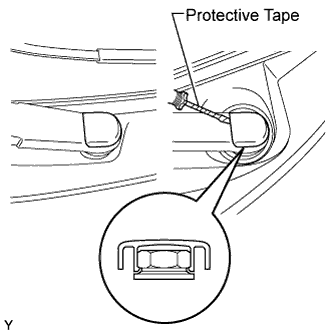
| 4. REMOVE FRONT WIPER ARM HEAD CAP |
Using a screwdriver with its tip wrapped in protective tape, disengage the claw and remove the 2 front wiper arm head caps.
| 5. REMOVE FRONT WIPER ARM AND BLADE ASSEMBLY LH |
Operate the wiper, then stop the windshield wiper motor in the automatic stop position.
Remove the nut and front wiper arm.
| 6. REMOVE FRONT WIPER ARM AND BLADE ASSEMBLY RH |
- HINT:
- Use the same procedure as for the LH side.
| 7. REMOVE COWL SIDE VENTILATOR SUB-ASSEMBLY LH |
Using a screwdriver with its tip wrapped in protective tape, disengage the 3 claws and remove the cowl side ventilator sub-assembly LH.
| 8. REMOVE COWL SIDE VENTILATOR SUB-ASSEMBLY RH |
- HINT:
- Use the same procedure as for the LH side.
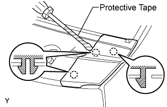
| 9. REMOVE COWL TOP VENTILATOR LOUVER SUB-ASSEMBLY |
Disengage the 3 clips, the 4 claws and the 8 hooks.
Remove the cowl top ventilator louver sub-assembly.
Disconnect the washer hoses.
Disengage the 5 hooks.
| 10. REMOVE FRONT WIPER MOTOR AND LINK |
Remove the 2 bolts.
Slide the wiper link. Disengage the meshing of the rubber pin, then disconnect the connector and remove the front wiper motor and link.
| 11. REMOVE FRONT AIR SHUTTER SEAL |
Disengage the 3 claws and remove the front air shutter seal.
| 12. REMOVE COWL TOP PANEL OUTER |
Disengage the claw and disconnect the wire harness.
Remove the 2 bolts and remove the cowl top panel outer center bracket.
Remove the 8 bolts and remove the cowl top panel outer.
| 13. REMOVE COLUMN HOLE COVER SILENCER SHEET |
Remove the floor carpet and 2 clips and remove the column hole cover silencer.
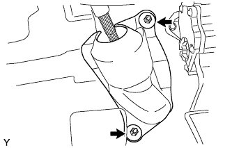
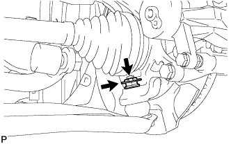
| 14. REMOVE STEERING SLIDING YOKE SUB-ASSEMBLY |
Use a seat belt to fix the steering wheel assembly, in order to avoid breakage of the spiral cable.
Place matchmarks on the sliding yoke of the steering intermediate shaft assembly and the steering gear assembly.
Text in Illustration*1
| Bolt A
|
*2
| Bolt B
|
*a
| Matchmark
|
Loosen bolt A, remove bolt B and separate the steering intermediate shaft assembly.
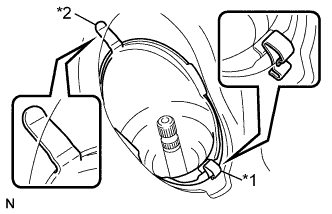
| 15. REMOVE NO. 1 STEERING COLUMN HOLE COVER SUB-ASSEMBLY |
Remove clip A, separate clip B from the body and separate No. 1 steering column hole cover sub-assembly.
Text in Illustration*1
| Clip A
|
*2
| Clip B
|
| 17. SEPARATE FRONT STABILIZER LINK ASSEMBLY LH |
Remove the nut and separate the stabilizer link from the shock absorber.
- HINT:
- If the ball joint turns together with the nut, use a socket hexagon wrench 6 to hold the stud.
| 18. SEPARATE FRONT STABILIZER LINK ASSEMBLY RH |
- HINT:
- Use the same procedure for the RH side as for the LH side.
| 19. SEPARATE TIE ROD END SUB-ASSEMBLY LH |
Remove the cotter pin and castle nut.
Using SST, separate the tie rod end from the steering knuckle.
- SST
- 09628-62011
- NOTICE:
- Do not damage the tie rod end dust cover.
| 20. SEPARATE TIE ROD END SUB-ASSEMBLY RH |
- HINT:
- Use the same procedure for the RH side as for the LH side.
| 21. SEPARATE FRONT SUSPENSION LOWER ARM LH |
Remove the clip and castle nut.
Using SST, separate the lower arm.
- SST
- 09628-00011
- NOTICE:
- Do not damage the lower ball joint dust cover.
- Suspend SST with a piece of string or the equivalent.
| 22. SEPARATE FRONT SUSPENSION LOWER ARM RH |
- HINT:
- Use the same procedure for the RH side as for the LH side.
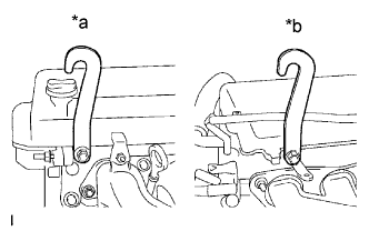
| 23. SUSPEND ENGINE ASSEMBLY |
Remove the bolt and remove the radio setting condenser.
Remove the bolt and remove the air-fuel ratio sensor wiring bracket.
Install the engine hanger with the bolt in the position shown in the illustration.
Text in Illustration*a
| Front Side
|
*b
| Rear Side
|
Part No.Engine Hanger
| 12281-21010
|
Bolt
| 91642-81025
|
- Torque:
- 40 N*m{408 kgf*cm, 30 ft.*lbf}
Using an engine sling device and a chain block, support the engine assembly w/transaxle and front suspension crossmember.
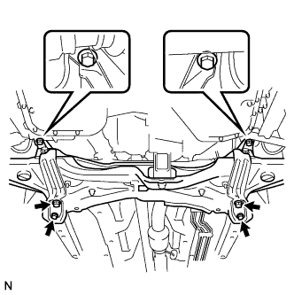
| 24. REMOVE FRONT SUSPENSION CROSSMEMBER SUB-ASSEMBLY |
Remove the bolt and separate the engine moving control rod.
Support the front suspension crossmember with a transmission jack.
Remove the 6 bolts and remove the suspension crossmember.
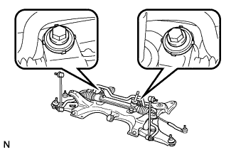
| 25. REMOVE STEERING GEAR ASSEMBLY |
Remove the 2 bolts and 2 nuts and remove the steering gear assembly from the suspension crossmember.
- NOTICE:
- Keep the nut from rotating while turning the bolt.
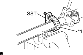
| 26. SECURE STEERING GEAR ASSEMBLY |
Using SST, secure the steering gear assembly in a vise.
Text in Illustration*1
| Protective Tape
|
- SST
- 09612-00012
- HINT:
- Tape SST before use.
| 27. REMOVE TIE ROD END SUB-ASSEMBLY LH |
Put matchmarks on the tie rod end sub-assembly LH and steering gear assembly.
Text in Illustration*a
| Matchmark
|
Remove the tie rod end sub-assembly LH and lock nut.
| 28. REMOVE TIE ROD END SUB-ASSEMBLY RH |
- HINT:
- Use the same procedure as for the LH side.