Meter / Gauge System (For Sedan) -- On-Vehicle Inspection |
| 1. INSPECT SPEEDOMETER |
Check the operation.
Using a speedometer tester, inspect the speedometer and confirm that the speedometer readings are within the acceptable range. Also check the odometer operation.
- Reference:
- km/h (Canada):
Standard Indication Acceptable Range 20 km/h 17.5 to 21.5 km/h 40 km/h 38 to 42 km/h 60 km/h 58 to 63 km/h 80 km/h 78 to 84 km/h 100 km/h 98.5 to 104.5 km/h 120 km/h 119 to 125 km/h 140 km/h 139 to 146 km/h 160 km/h 159 to 167 km/h 180 km/h 179 to 188 km/h 200 km/h 199 to 209 km/h - mph (U.S.A.):
Standard Indication Acceptable Range 20 mph 18 to 21 mph 40 mph 38.5 to 42 mph 60 mph 59 to 63 mph 80 mph 79.5 to 84 mph 100 mph 100 to 105 mph 120 mph 121 to 126.5 mph
- NOTICE:
- Tire wear and excessively high or low tire pressure affect speedometer indications.
Check the deflection of the speedometer indicator.
- Reference:
- Below 0.3 mph (0.5 km/h)
| 2. INSPECT SPEEDOMETER SENSOR |
 |
Check the output signal waveform.
Remove the combination meter assembly, but do not disconnect the connector.
Connect an oscilloscope to terminals D1-16 and to the body ground.
Start the engine.
Check the signal waveform according to the condition(s) in the table below.
Item Contents Terminal Connection +S (D1-16) and Body Ground Tool Setting 5 V/DIV, 20 ms/DIV Condition Driving at approximately 12mph (20km / h) - OK:
- As shown in the illustration.
- NOTICE:
- Waveform is indicated as the vehicle speed increases, the cycle of the signal waveform narrows.
Reinstall the combination meter assembly.
| 3. INSPECT TACHOMETER |
Check the operation.
Connect the Techstream to the DLC3.
Turn the ignition switch ON and turn the tester ON.
Select the item below from the Data List and read the value displayed on the Techstream.
Body Electrical / Combination Meter / Data List: Tester Display Measurement Item/Range Normal Condition Diagnostic Note Engine Rpm Engine speed/Min.: 0 rpm, Max.:12,750 rpm Approximately same as actual engine speed (When engine is running) - Compare the engine speed displayed on the tester with the tachometer reading.
- Reference:
Standard Indication (r/min) Acceptable Range
[Data in ( ) are for reference]700 r/min 630 to 770 r/min 1,000 r/min (900 to 1,100 r/min) 2,000 r/min (1,850 to 2,150 r/min) 3,000 r/min 2,800 to 3,200 r/min 4,000 r/min (3,800 to 4,200 r/min) 5,000 r/min 4,800 to 5,200 r/min 6,000 r/min (5,750 to 6,250 r/min) 7,000 r/min (6,700 to 7,300 r/min)
| 4. INSPECT FUEL RECEIVER GAUGE |
Disconnect the J5 fuel sender gauge connector.
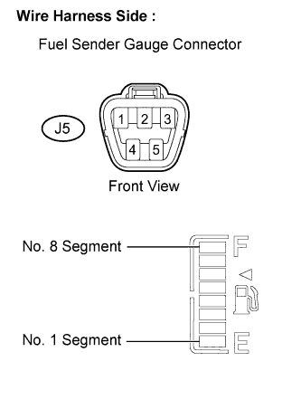 |
Check the fuel receiver gauge operation when the ignition switch is turned to the ON position.
- OK:
- No. 1 segment flashes.
Connect terminals 2 and 3 on the wire harness side connector of the fuel sender gauge.
Check the fuel receiver gauge operation when the ignition switch is turned from OFF to ON.
- OK:
- All segments, from No. 1 to No. 8, illuminate.
Reconnect the fuel sender gauge connector.
| 5. INSPECT FUEL LEVEL WARNING LIGHT |
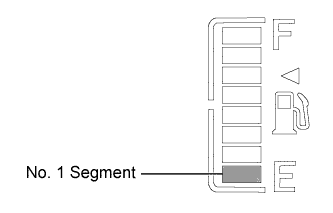 |
Turn the ignition switch to the ON position, and check that the receiver gauge No. 1 segment flashes when the fuel volume is less than 6.3 liters (less than 15 % of the total fuel tank capacity).
- OK:
Fuel Volume Flashing Speed (Interval) 1.6 gal (6.3 liters) (Less than 15 % of total fuel tank capacity) Flashes slowly (1.2 seconds) 1.1 gal (4.2 liters) (Less than 10 % of total fuel tank capacity) Flashes quickly (0.6 seconds)
| 6. INSPECT ENGINE OIL PRESSURE WARNING LIGHT |
Disconnect the engine oil pressure switch connector.
Turn the ignition switch to the ON position.
Ground the terminal of the wire harness side connector, then check the engine oil pressure warning light.
- OK:
- Engine oil pressure warning light illuminates.
Reconnect the engine oil pressure switch connector.
| 7. INSPECT BRAKE WARNING LIGHT |
Inspect the parking brake warning light.
Disconnect the parking brake switch connector.
Turn the ignition switch to the ON position.
Ground the terminal of the wire harness side connector, then check the parking brake warning light.
- OK:
- Brake warning light illuminates.
Reconnect the parking brake switch connector.
Inspect the brake fluid level warning light.
Disconnect the brake fluid level warning switch connector.
Turn the ignition switch to the ON position.
Connect a terminal to the other terminal of the wire harness side connector, then check the brake fluid level warning switch.
- OK:
- Brake warning light illuminates.
Reconnect the brake fluid level warning switch connector.
| 8. INSPECT BRAKE FLUID LEVEL WARNING SWITCH |
Remove the reservoir tank cap and strainer.
Disconnect the brake fluid level warning switch connector.
Measure the resistance between the terminals.
- Standard resistance:
- Float inside reservoir tank is in high position (switch OFF): 10 k Ω or higher
Use a siphon or a similar tool to drain fluid out of the reservoir tank.
Measure the resistance between the terminals.
- Standard resistance:
- Float inside reservoir tank is in low position (switch ON): Below 1 Ω
Pour the fluid back into the reservoir tank.
Reconnect the brake fluid level warning switch connector.
Reinstall the reservoir tank cap and strainer.
| 9. INSPECT WINDOW WASHER FLUID WARNING LIGHT |
Disconnect the connector from the washer level warning switch.
Turn the ignition switch to the ON position.
Ground the terminal of the wire harness side connector, then check the washer level warning light.
- OK:
- Washer level warning light comes on.
| 10. INSPECT ENGINE COOLANT TEMPERATURE WARNING LIGHT |
Disconnect the engine coolant temperature sensor connector.
Turn the ignition switch to the ON position.
Connect a terminal to the other terminal of the wire harness side connector, then check the engine coolant temperature warning light.
- OK:
- Engine coolant temperature warning light illuminates.
Reconnect the engine coolant temperature sensor connector.
- NOTICE:
- DTCs may have been set. Check for DTCs and clear any that have been set.