Rear View Monitor System (W/O Navigation System) Inner Rear View Mirror Power Source Circuit
DESCRIPTION
WIRING DIAGRAM
INSPECTION PROCEDURE
CHECK HARNESS AND CONNECTOR (INNER REAR VIEW MIRROR ASSEMBLY - BATTERY AND BODY GROUND)
REAR VIEW MONITOR SYSTEM (w/o Navigation System) - Inner Rear View Mirror Power Source Circuit |
DESCRIPTION
This is the power source circuit of the inner rear view mirror assembly.
WIRING DIAGRAM
INSPECTION PROCEDURE
- NOTICE:
- Inspect the fuses for circuits related to this system before performing the following inspection procedure.
| 1.CHECK HARNESS AND CONNECTOR (INNER REAR VIEW MIRROR ASSEMBLY - BATTERY AND BODY GROUND) |
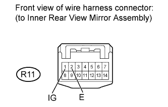
Disconnect the R11 inner rear view mirror assembly connector.
Measure the voltage according to the value(s) in the table below.
- Standard Voltage:
Tester Connection
| Switch Condition
| Specified Condition
|
R11-1 (IG) - Body ground
| Ignition switch ON
| 11 to 14 V
|
Ignition switch off
| Below 1 V
|
Measure the resistance according to the value(s) in the table below.
- Standard Resistance:
Tester Connection
| Condition
| Specified Condition
|
R11-2 (E) - Body ground
| Always
| Below 1 Ω
|
| | REPAIR OR REPLACE HARNESS OR CONNECTOR |
|
|