INSPECT NAVIGATION RECEIVER ASSEMBLY
CHECK HARNESS AND CONNECTOR (NAVIGATION RECEIVER - MAP LIGHT)
REPLACE TELEPHONE MICROPHONE WITH ANOTHER AND CHECK
NAVIGATION SYSTEM (for DVD) - Microphone Circuit between Microphone and Navigation Receiver Assembly |
DESCRIPTION
This circuit sends a microphone signal from the telephone microphone assembly to the navigation receiver assembly.It also supplies power from the navigation receiver assembly to the telephone microphone assembly.
WIRING DIAGRAM


INSPECTION PROCEDURE
| 1.INSPECT NAVIGATION RECEIVER ASSEMBLY |
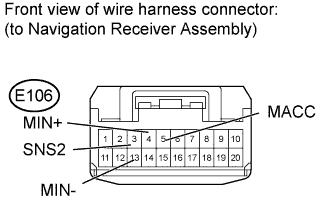
for 3ZR-FAE:
Disconnect the E106 navigation receiver assembly connector.
Measure the resistance according to the value(s) in the table below.
- Standard Resistance:
Tester Connection Switch Condition Specified Condition 13 (MIN-) - Body ground Always Below 1 Ω
Measure the voltage according to the value(s) in the table below.
- Standard Voltage:
Tester Connection Switch Condition Specified Condition 5 (MACC) - Body ground Ignition switch ACC 4.75 to 5.25 V

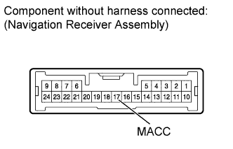
except 3ZR-FAE:
Disconnect the E54 navigation receiver assembly connector.
Measure the voltage according to the value(s) in the table below.
- Standard Voltage:
Tester Connection Switch Condition Specified Condition 17 (MACC) - Body ground Ignition switch ACC 4.75 to 5.25 V
|
| ||||
| OK | |
| 2.CHECK HARNESS AND CONNECTOR (NAVIGATION RECEIVER - MAP LIGHT) |
for 3ZR-FAE:
Disconnect the E106 navigation receiver assembly connector.
Disconnect the R8 map light connector.
Measure the resistance according to the value(s) in the table below.
- Standard Resistance:
Tester Connection Condition Specified Condition E106-5 (MACC) - R8-12 (ACC) Always Below 1 Ω E106-4 (MIN+) - R8-11 (MI1+) Always Below 1 Ω E106-13 (MIN-) - R8-10 (MIC-) Always Below 1 Ω E106-5 (MACC) - Body ground Always 10 kΩ or higher E106-4 (MIN+) - Body ground Always 10 kΩ or higher E106-13 (MIN-) - Body ground Always 10 kΩ or higher E106-3 (SNS2) - Body ground Always Below 1 Ω

except 3ZR-FAE:
Disconnect the E54 navigation receiver assembly connector.
Disconnect the R8 map light connector.
Measure the resistance according to the value(s) in the table below.
- Standard Resistance:
Tester Connection Condition Specified Condition E54-17 (MACC) - R8-12 (ACC) Always Below 1 Ω E54-19 (MIC+) - R8-11 (MI1+) Always Below 1 Ω E54-20 (MIC-) - R8-10 (MIC-) Always Below 1 Ω E54-17 (MACC) - Body ground Always 10 kΩ or higher E54-19 (MIC+) - Body ground Always 10 kΩ or higher E54-20 (MIC-) - Body ground Always 10 kΩ or higher

|
| ||||
| OK | |
| 3.REPLACE TELEPHONE MICROPHONE WITH ANOTHER AND CHECK |
Replace the telephone microphone with a new or normally functioning one (RAV4_ACA30 RM0000021PU001X.html).
Check if the same problem occurs again.
|
| ||||
| OK | ||
| ||