Dtc P2769 Short In Torque Converter Clutch Solenoid Circuit (Shift Solenoid Valve Sl)
K111F Cvt. Toyota Rav4. Aca30, 33, 38 Gsa33 Zsa30, 35
DESCRIPTION
MONITOR DESCRIPTION
WIRING DIAGRAM
INSPECTION PROCEDURE
INSPECT TRANSMISSION WIRE (SHIFT SOLENOID VALVE SL)
CHECK HARNESS AND CONNECTOR (TRANSMISSION WIRE - ECM)
REPLACE ECM
PERFORM INITIALIZATION
REPLACE CONTINUOUSLY VARIABLE TRANSAXLE ASSEMBLY
PERFORM INITIALIZATION
DTC P2769 Short in Torque Converter Clutch Solenoid Circuit (Shift Solenoid Valve SL) |
DTC P2770 Open in Torque Converter Clutch Solenoid Circuit (Shift Solenoid Valve SL) |
DESCRIPTION
The ECM turns shift solenoid valve SL on or off to control the oil pressure applied to the lock-up relay valve and turns lock-up on or off.DTC Code
| DTC Detection Condition
- Diagnosis Condition
- Malfunction Status
- Malfunction Time
- Other
| Trouble Area
|
P2769
| - Lock-up is operating.
- There is a short circuit in the shift solenoid valve SL circuit.
- Detected 2 times or more consecutively
- 2 trip detection logic
| - Short in shift solenoid valve SL circuit
- Continuously variable transaxle assembly
- ECM
|
P2770
| - Lock-up is operating.
- There is an open circuit in the shift solenoid valve SL circuit.
- Detected 2 times or more consecutively
- 2 trip detection logic
| - Open in shift solenoid valve SL circuit
- Continuously variable transaxle assembly
- ECM
|
MONITOR DESCRIPTION
These DTCs indicate an open or short circuit in the shift solenoid valve SL circuit. When there is an open or short circuit in the shift solenoid valve SL circuit, the ECM detects the problem, illuminates the MIL and stores the DTC.
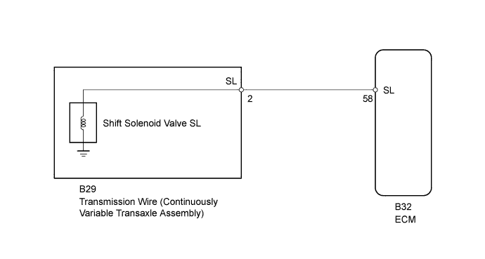
WIRING DIAGRAM
INSPECTION PROCEDURE
| 1.INSPECT TRANSMISSION WIRE (SHIFT SOLENOID VALVE SL) |
Disconnect the transmission wire connector.
Measure the resistance according to the value(s) in the table below.
- Standard Resistance:
Tester Connection
| Condition
| Specified Condition
|
2 (SL) - Body ground
| 20°C (68°F)
| 11 to 15 Ω
|
Text in Illustration*1
| Component without harness connected
(Transmission Wire)
|
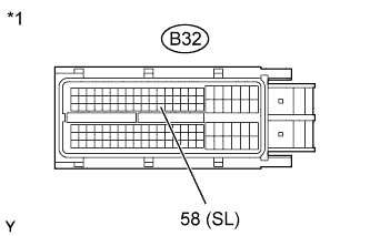
| 2.CHECK HARNESS AND CONNECTOR (TRANSMISSION WIRE - ECM) |
Disconnect the ECM connector.
Measure the resistance according to the value(s) in the table below.
- Standard Resistance:
Tester Connection
| Condition
| Specified Condition
|
B32-58 (SL) - Body ground
| 20°C (68°F)
| 11 to 15 Ω
|
Text in Illustration*1
| Front view of wire harness connector
(to ECM)
|
| | REPAIR OR REPLACE HARNESS OR CONNECTOR |
|
|
Replace the ECM (RAV4_ACA30 RM0000017UO01KX.html).
- NOTICE:
- Performing reset memory will clear the learned values of both the yaw rate sensor assembly*1 or deceleration sensor*2 (deceleration sensor 0 point calibration) and CVT oil pressure (CVT oil pressure calibration). Make sure to perform reset memory, yaw rate sensor assembly*1 or deceleration sensor*2 0 point calibration and CVT oil pressure calibration when replacing any of the parts shown in the following table:
Replaced Part
|
- Continuously variable transaxle assembly
- ECM
- Oil pressure sensor
- Yaw rate sensor assembly (w/ VSC)
- Deceleration sensor (w/o VSC)
- Brake actuator assembly (skid control ECU)
|
- After performing reset memory, always perform yaw rate sensor assembly*1 or deceleration sensor*2 (deceleration sensor 0 point) calibration first, and then CVT oil pressure calibration.
- Always perform 0 point calibration with the vehicle on level ground.
- Do not shake or vibrate the vehicle during 0 point calibration.
Using the intelligent tester, perform reset memory, deceleration sensor 0 point calibration and CVT oil pressure calibration (RAV4_ACA30 RM000003UQR002X.html).
Check that no DTC is stored.
| 5.REPLACE CONTINUOUSLY VARIABLE TRANSAXLE ASSEMBLY |
Replace the continuously variable transaxle assembly (RAV4_ACA30 RM00000192D01ZX.html).
- NOTICE:
- Performing reset memory will clear the learned values of both the yaw rate sensor assembly*1 or deceleration sensor*2 (deceleration sensor 0 point calibration) and CVT oil pressure (CVT oil pressure calibration). Make sure to perform reset memory, yaw rate sensor assembly*1 or deceleration sensor*2 0 point calibration and CVT oil pressure calibration when replacing any of the parts shown in the following table:
Replaced Part
|
- Continuously variable transaxle assembly
- ECM
- Oil pressure sensor
- Yaw rate sensor assembly (w/ VSC)
- Deceleration sensor (w/o VSC)
- Brake actuator assembly (skid control ECU)
|
- After performing reset memory, always perform yaw rate sensor assembly*1 or deceleration sensor*2 (deceleration sensor 0 point) calibration first, and then CVT oil pressure calibration.
- Always perform 0 point calibration with the vehicle on level ground.
- Do not shake or vibrate the vehicle during 0 point calibration.
Using the intelligent tester, perform reset memory, deceleration sensor 0 point calibration and CVT oil pressure calibration (RAV4_ACA30 RM000003UQR002X.html).
Check that no DTC is stored.