Dtc P0660 Intake Manifold Tuning Valve Control Circuit / Open (Bank 1)
Engine. Toyota Rav4. Aca30, 33, 38 Gsa33 Zsa30, 35
DESCRIPTION
WIRING DIAGRAM
INSPECTION PROCEDURE
PERFORM ACTIVE TEST USING INTELLIGENT TESTER
CHECK INTAKE AIR CONTROL VALVE (ACIS OPERATION)
INSPECT ACIS ACTUATOR (POWER SOURCE)
CHECK HARNESS AND CONNECTOR
DTC P0660 Intake Manifold Tuning Valve Control Circuit / Open (Bank 1) |
DESCRIPTION
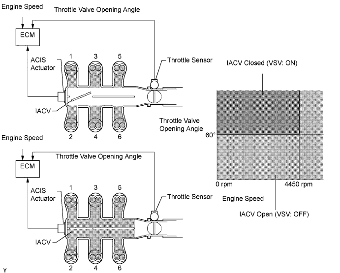
This circuit opens and closes the Intake Air Control Valve (IACV) in response to changes in the engine load in order to increase the intake efficiency (ACIS: Acoustic Control Induction System).When the engine speed is between 0 and 4450 rpm and the throttle valve opening angle is 60° or more, the ECM supplies current to the VSV (ON status), to close the IACV. Under other conditions, the VSV is usually OFF and the IACV is open.DTC No.
| DTC Detection Condition
| Trouble Area
|
P0660
| The following conditions are met simultaneously for 0.5 seconds or more (2 trip detection logic):
- Voltage of terminal ACIS of the ECM is low when the VSV is OFF
- The engine has been started
| - Open or short in intake manifold tuning valve control circuit
- Surge tank (intake air control valve)
- ECM
|
WIRING DIAGRAM
INSPECTION PROCEDURE
| 1.PERFORM ACTIVE TEST USING INTELLIGENT TESTER |
Connect the intelligent tester to the DLC3.
Start the engine and turn the tester on.
Select the following menu items: Powertrain / Engine and ECT / Active Test / Active the VSV for Intake Control.
Check if operating noise can be heard when operating the air intake control valve using the intelligent tester.
- OK:
- Operating noise can be heard.
| 2.CHECK INTAKE AIR CONTROL VALVE (ACIS OPERATION) |
Disconnect the ACIS actuator connector.
Apply battery voltage between the terminals of the ACIS actuator connector.
Check intake air control valve operation.
- OK:
- Operating noise can be heard.
| | REPLACE INTAKE AIR SURGE TANK ASSEMBLY |
|
|
| 3.INSPECT ACIS ACTUATOR (POWER SOURCE) |
Disconnect the ACIS actuator connector.
Turn the ignition switch to the ON position.
Measure the voltage between the terminals of the AICS actuator connector.
- Standard voltage:
Tester Connection
| Specified Condition
|
1 - 2
| 9 to 14 V
|
| | REPAIR OR REPLACE HARNESS OR CONNECTOR (EFI NO. 1 FUSE - ACIS ACTUATOR) |
|
|
| 4.CHECK HARNESS AND CONNECTOR |
Disconnect the ACIS actuator connector.
Disconnect the ECM connector.
Measure the resistance between the terminals of the ACIS connector and ECM connector.
- Standard resistance (Check for open):
Tester Connection
| Specified Condition
|
ACIS actuator (B92-1) - ACIS (B96-107)
| Below 1 Ω
|
- Standard resistance (Check for short):
Tester Connection
| Specified Condition
|
ACIS actuator (B92-1) or ACIS (B96-107) - Body ground
| 10 kΩ or higher
|
Reconnect the ECM connector.
Reconnect the ACIS connector.
| | REPAIR OR REPLACE HARNESS OR CONNECTOR |
|
|