Body Electrical. Toyota Rav4. Aca30, 33, 38 Gsa33 Zsa30, 35
Lighting. Toyota Rav4. Aca30, 33, 38 Gsa33 Zsa30, 35
Turn Signal Flasher Assembly -- On-Vehicle Inspection |
| 1. INSPECT TURN SIGNAL FLASHER CIRCUIT (for LHD) |
Check the power source circuit and ground circuit.
Remove the turn signal flasher relay from the instrument panel junction block.
Measure the voltage and resistance of the instrument panel junction block.
- Standard voltage:
Tester Connection Condition Specified Condition Turn signal flasher relay terminal 1 (IG) - Body ground Ignition switch off Below 1 V Turn signal flasher relay terminal 1 (IG) - Body ground Ignition switch on (IG) 10 to 14 V Turn signal flasher relay terminal 4 (+B) - Body ground Always 10 to 14 V
- Standard resistance:
Tester Connection Specified Condition Turn signal flasher relay terminal 7 (GND) - Body ground Below 1 Ω
 |
Check the output operation signal.
Install the turn signal flasher relay onto the instrument panel junction block.

Measure the voltage of the instrument panel junction block.
- Standard voltage:
Tester Connection Condition Specified Condition IA-27 (LL) - Body ground Hazard warning switch OFF → ON 0 V → 10 to 14 V (60 to 120 times per minute) IA-27 (LL) - Body ground Turn signal switch (left turn) OFF → ON 0 V → 10 to 14 V (60 to 120 times per minute) IA-28 (LR) - Body ground Hazard warning switch OFF → ON 0 V → 10 to 14 V (60 to 120 times per minute) IA-28 (LR) - Body ground Turn signal switch (right turn) OFF → ON 0 V → 10 to 14 V (60 to 120 times per minute) IB-14 (LL) - Body ground Hazard warning switch OFF → ON 0 V → 10 to 14 V (60 to 120 times per minute) IB-14 (LL) - Body ground Turn signal switch (left turn) OFF → ON 0 V → 10 to 14 V (60 to 120 times per minute) IB-31 (LR) - Body ground Hazard warning switch OFF → ON 0 V → 10 to 14 V (60 to 120 times per minute) IB-31 (LR) - Body ground Turn signal switch (right turn) OFF → ON 0 V → 10 to 14 V (60 to 120 times per minute) IS-11 (EL) - Body ground Turn signal switch (left turn) OFF → ON 10 to 14 V → 0 V IS-12 (ER) - Body ground Turn signal switch (right turn) OFF → ON 10 to 14 V → 0 V IS-13 (LL) - Body ground Hazard warning switch OFF → ON 0 V → 10 to 14 V (60 to 120 times per minute) IS-13 (LL) - Body ground Turn signal switch (left turn) OFF → ON 0 V → 10 to 14 V (60 to 120 times per minute) IS-16 (LR) - Body ground Hazard warning switch OFF → ON 0 V → 10 to 14 V (60 to 120 times per minute) IS-16 (LR) - Body ground Turn signal switch (right turn) OFF → ON 0 V → 10 to 14 V (60 to 120 times per minute) IS-17 (EHW) - Body ground Hazard warning switch OFF → ON 10 to 14 V → 0 V
| 2. INSPECT TURN SIGNAL FLASHER CIRCUIT (for RHD) |
 |
Check the power source circuit and ground circuit.
Remove the turn signal flasher assembly.
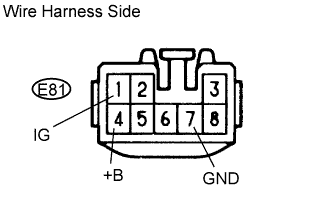
Measure the voltage and resistance of the wire harness side connector.
- Standard Voltage:
Tester Connection Condition Specified Condition E81-1 (IG) - Body ground Ignition switch off 0 V E81-1 (IG) - Body ground Ignition switch on (IG) 10 to 14 V E81-4 (+B) - Body ground Always 10 to 14 V
- Standard Resistance:
Tester Connection Condition Specified Condition E81-7 (GND) - Body ground Always Below 1 Ω
Check the output operation signal.
Install the turn signal flasher relay.
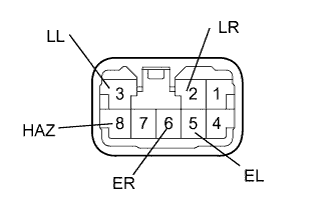
Measure the voltage of the turn signal flasher relay.
- Standard:
Tester Connection Condition Specified Condition 2 (LR) - Body ground Hazard warning switch OFF → ON 0 V → 10 to 14 V (60 to 120 times per minute) 2 (LR) - Body ground Turn signal switch (right turn) OFF → ON 0 V → 10 to 14 V (60 to 120 times per minute) 3 (LL) - Body ground Hazard warning switch OFF → ON 0 V → 10 to 14 V (60 to 120 times per minute) 3 (LL) - Body ground Turn signal switch (left turn) OFF → ON 0 V → 10 to 14 V (60 to 120 times per minute) 5 (EL) - Body ground Turn signal switch (left turn) OFF → ON 10 to 14 V → 0 V 6 (ER) - Body ground Turn signal switch (right turn) OFF → ON 10 to 14 V → 0 V 8 (HAZ) - Body ground Hazard warning switch OFF → ON 10 to 14 V → 0 V