Sfi System Acis Control Circuit
Engine. Toyota Rav4. Aca30, 33, 38 Gsa33 Zsa30, 35
DESCRIPTION
WIRING DIAGRAM
INSPECTION PROCEDURE
PERFORM ACTIVE TEST USING INTELLIGENT TESTER (OPERATE VSV FOR ACIS)
CHECK VACUUM HOSES (VACUUM SWITCHING VALVE - INTAKE AIR CONTROL VALVE, INTAKE MANIFOLD)
INSPECT INTAKE MANIFOLD (INTAKE AIR CONTROL VALVE)
INSPECT VACUUM SWITCHING VALVE (for ACIS)
CHECK HARNESS AND CONNECTOR (VACUUM SWITCHING VALVE - ECM AND INTEGRATION RELAY)
CHECK ECM POWER SOURCE CIRCUIT
SFI SYSTEM - ACIS Control Circuit |
DESCRIPTION
This circuit opens and closes the Intake Air Control Valve (IACV) in response to the engine load in order to increase the intake efficiency (ACIS: Acoustic Control Induction System).Text in Illustration*1
| Intake Air Control Valve Open
| *2
| Intake Air Control Valve Closed
|
WIRING DIAGRAM
INSPECTION PROCEDURE
- NOTICE:
- Inspect the fuses for circuits related to this system before performing the following inspection procedure.
| 1.PERFORM ACTIVE TEST USING INTELLIGENT TESTER (OPERATE VSV FOR ACIS) |
Disconnect the vacuum hose from port F of the vacuum switching valve (for ACIS).
Connect the intelligent tester to the DLC3.
Start the engine.
Enter the following menus: Powertrain / Engine and ECT / Active Test / Active the VSV for Intake Control.
Operate the VSV for ACIS.
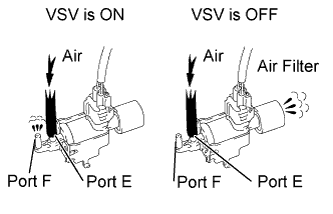
Check the VSV air flow when switching the VSV on and off.
- OK:
Test Condition
| Specified Condition
|
VSV is ON
| Air from port E flows out through port F
|
VSV is OFF
| Air from port E flows out through air filter
|
| 2.CHECK VACUUM HOSES (VACUUM SWITCHING VALVE - INTAKE AIR CONTROL VALVE, INTAKE MANIFOLD) |
Check the vacuum hoses (RAV4_ACA30 RM00000341000BX_01_0001.html).
| | REPAIR OR REPLACE VACUUM HOSES |
|
|
| 3.INSPECT INTAKE MANIFOLD (INTAKE AIR CONTROL VALVE) |
Inspect the intake air control valve (RAV4_ACA30 RM00000341000BX_01_0002.html).
| 4.INSPECT VACUUM SWITCHING VALVE (for ACIS) |
Inspect the vacuum switching valve (for ACIS) (RAV4_ACA30 RM000003UP5001X_01_0001.html).
| | REPLACE VACUUM SWITCHING VALVE |
|
|
| 5.CHECK HARNESS AND CONNECTOR (VACUUM SWITCHING VALVE - ECM AND INTEGRATION RELAY) |
Disconnect the intake air control valve connector.
Disconnect the ECM connector.
Remove the integration relay from the engine room No. 1 relay block.
Disconnect the integration relay connector.
Measure the resistance according to the value(s) in the table below.
- Standard Resistance (Check for Open):
Tester Connection
| Condition
| Specified Condition
|
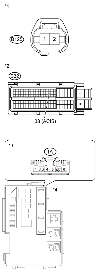
B125-1 - B32-38 (ACIS)
| Always
| Below 1 Ω
|
B125-2 - 1A-4
| Always
| Below 1 Ω
|
- Standard Resistance (Check for Short):
Tester Connection
| Condition
| Specified Condition
|
B125-1 or B32-38 (ACIS) - Body ground
| Always
| 10 kΩ or higher
|
B125-2 or 1A-4 - Body ground
| Always
| 10 kΩ or higher
|
Text in Illustration*1
| Front view of wire harness connector
(to VSV for ACIS)
|
*2
| Front view of wire harness connector
(to ECM)
|
*3
| Front view of wire harness connector
(to Integration Relay)
|
*4
| Engine Room No. 1 Relay Block
|
Reconnect the intake air control valve connector.
Reconnect the ECM connector.
Reconnect the integration relay connector.
Install the integration relay.
| | REPAIR OR REPLACE HARNESS OR CONNECTOR (VACUUM SWITCHING VALVE - ECM AND INTEGRATION RELAY) |
|
|
| 6.CHECK ECM POWER SOURCE CIRCUIT |
Check the ECM power source circuit (RAV4_ACA30 RM00000276902PX.html).
| | REPAIR ECM POWER SOURCE CIRCUIT |
|
|