Lighting. Toyota Rav4. Aca30, 33, 38 Gsa33 Zsa30, 35
DESCRIPTION
WIRING DIAGRAM
INSPECTION PROCEDURE
INSPECT VEHICLE CONDITION
CHECK OPERATION OF TURN SIGNAL LIGHT
INSPECT FUSE (ECU-IG2, HAZ)
CHECK WIRE HARNESS (BATTERY - TURN SIGNAL FLASHER RELAY)
INSPECT HEADLIGHT DIMMER SWITCH
CHECK WIRE HARNESS (TURN SIGNAL FLASHER RELAY - DIMMER SWITCH AND BODY GROUND)
INSPECT BULB (FRONT TURN SIGNAL BULB)
CHECK WIRE HARNESS (TURN SIGNAL FLASHER RELAY - FRONT TURN SIGNAL LIGHT)
INSPECT DOOR MIRROR TURN SIGNAL LIGHT
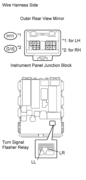
CHECK WIRE HARNESS (OUTER REAR VIEW MIRROR - TURN SIGNAL FLASHER RELAY)
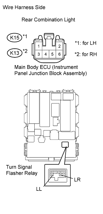
INSPECT REAR COMBINATION LIGHT
CHECK WIRE HARNESS (TURN SIGNAL FLASHER RELAY - REAR COMBINATION LIGHT)
CHECK OPERATION OF TURN SIGNAL LIGHT
INSPECT FUSE (ECU-IG2, HAZ)
CHECK WIRE HARNESS (TURN SIGNAL FLASHER RELAY - BATTERY)
INSPECT HEADLIGHT DIMMER SWITCH
CHECK WIRE HARNESS (TURN SIGNAL FLASHER RELAY - DIMMER SWITCH)
INSPECT FRONT TURN SIGNAL LIGHT BULB
CHECK WIRE HARNESS (INSTRUMENT PANEL JUNCTION BLOCK - FRONT TURN SIGNAL LIGHT)
INSPECT FRONT SIDE TURN SIGNAL LIGHT BULB
CHECK WIRE HARNESS (JUNCTION BLOCK - FRONT SIDE TURN SIGNAL LIGHT)
INSPECT REAR COMBINATION LIGHT
CHECK WIRE HARNESS (INSTRUMENT PANEL JUNCTION BLOCK - REAR COMBINATION LIGHT)
INSPECT DOOR MIRROR TURN SIGNAL LIGHT
CHECK WIRE HARNESS (INSTRUMENT PANEL JUNCTION BLOCK - OUTER REAR VIEW MIRROR)
INSPECT FRONT SIDE TURN SIGNAL LIGHT BULB
CHECK WIRE HARNESS (TURN SIGNAL FLASHER RELAY - FRONT SIDE TURN SIGNAL LIGHT)
LIGHTING SYSTEM - Turn Signal Light Circuit |
DESCRIPTION
The turn signal flasher relay (marking for LHD: turn signal flasher) turns on when it receives signals from the headlight dimmer switch integrated with the turn signal switch, causing the turn signal lights to flash.
WIRING DIAGRAM
INSPECTION PROCEDURE
| 1.INSPECT VEHICLE CONDITION |
Check the vehicle condition.
ResultResult
| Proceed to
|
RHD
| A
|
LHD
| B
|
| 2.CHECK OPERATION OF TURN SIGNAL LIGHT |
When the turn signal light switch is operated, check that the appropriate turn signal light flashes.
ResultCondition
| Proceed to
|
All lights do not flash
| A
|
Front turn signal light (LH or RH) does not flash
| B
|
Door mirror turn signal light (LH or RH) does not flash*2
| C
|
Rear turn signal light (LH or RH) does not flash
| D
|
Front side turn signal light (LH or RH) does not flash*1
| E
|
*1: w/o Door Mirror Turn Signal Light
*2: w/ Door Mirror Turn Signal Light
| 3.INSPECT FUSE (ECU-IG2, HAZ) |
Remove the ECU-IG2 fuse from the instrument panel junction block.
Remove the HAZ fuse from the engine room No. 1 relay block.
Measure the resistance of the fuse.
- Standard resistance:
- Below 1 Ω
| 4.CHECK WIRE HARNESS (BATTERY - TURN SIGNAL FLASHER RELAY) |
Disconnect the E81 turn signal flasher relay connector.
Measure the voltage of the wire harness side connector.
- Standard voltage:
Tester Connection
| Condition
| Specified Condition
|
E81-1 (IG) - Body ground
| Ignition switch on (IG)
| 11 to 14 V
|
E81-4 (B) - Body ground
| Always
| 11 to 14 V
|
| | REPAIR OR REPLACE HARNESS AND CONNECTOR |
|
|
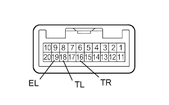
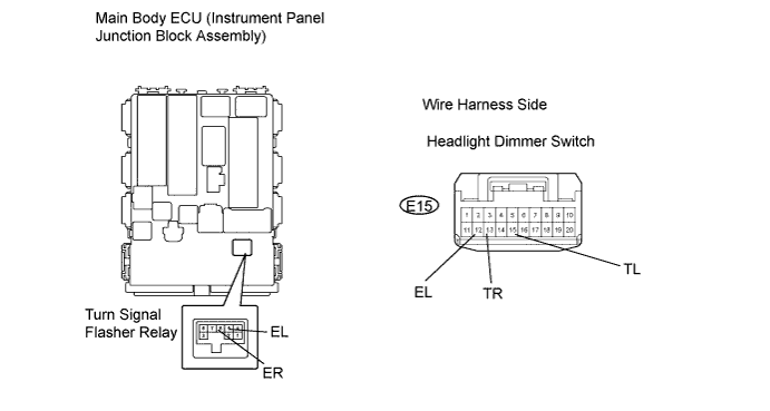
| 5.INSPECT HEADLIGHT DIMMER SWITCH |
Remove the headlight dimmer switch.
Measure the resistance of the switch.
- Standard resistance:
Tester Connection
| Condition
| Specified Condition
|
16 (TR) - 19 (EL)
| Right turn
| Below 1 Ω
|
18 (TL) - 19 (EL)
| Left turn
| Below 1 Ω
|
16 (TR) - 19 (EL)
| Neutral
| 10 kΩ or higher
|
18 (TL) - 19 (EL)
| Neutral
| 10 kΩ or higher
|
| | REPLACE HEADLIGHT DIMMER SWITCH ASSEMBLY |
|
|
| 6.CHECK WIRE HARNESS (TURN SIGNAL FLASHER RELAY - DIMMER SWITCH AND BODY GROUND) |
Disconnect the E15 headlight dimmer switch connector.
Disconnect the E81 turn signal flasher relay connector.
Measure the resistance of the wire harness side connectors.
- Standard resistance:
Tester Connection
| Specified Condition
|
E15-16 (TR) - E81-6 (ER)
| Below 1 Ω
|
E15-16 (TR) or E81-6 (ER) - Body ground
| 10 kΩ or higher
|
E15-18 (TL) - E81-5 (EL)
| Below 1 Ω
|
E15-18 (TL) or - E81-5 (EL) - Body ground
| 10 kΩ or higher
|
E15-19 (EL) - Body ground
| Below 1 Ω
|
| | REPAIR OR REPLACE HARNESS AND CONNECTOR |
|
|
| OK |
|
|
|
| REPLACE TURN SIGNAL FLASHER RELAY |
|
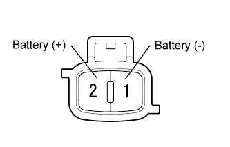
| 7.INSPECT BULB (FRONT TURN SIGNAL BULB) |
Remove the front turn signal light bulb.
Connect the positive (+) lead from the battery to terminal 2 and the negative (-) lead to terminal 1, then check that the bulb illuminates.
- OK:
- Bulb illuminates.
| | REPLACE FRONT TURN SIGNAL LIGHT BULB |
|
|
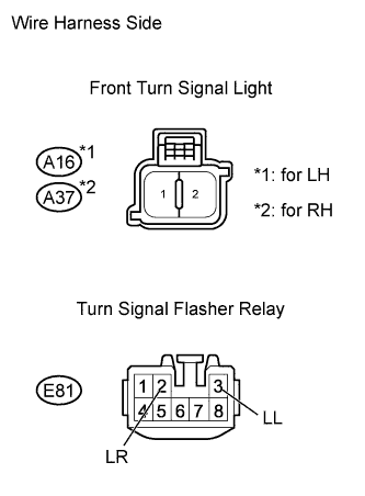
| 8.CHECK WIRE HARNESS (TURN SIGNAL FLASHER RELAY - FRONT TURN SIGNAL LIGHT) |
Disconnect the A16 (for LH) and A37 (for RH) front turn signal light connectors.
Disconnect the E81 turn signal flasher relay connector.
Measure the resistance of the wire harness side connectors.
- Standard resistance:
for LH side:Tester Connection
| Specified Condition
|
E81-3 (LL) - A16-2
| Below 1 Ω
|
E81-3 (LL) or A16-2 - Body ground
| 10 kΩ or higher
|
for RH side:Tester Connection
| Specified Condition
|
E81-2 (LR) - A37-2
| Below 1 Ω
|
E81-2 (LR) or A37-2 - Body ground
| 10 kΩ or higher
|
| | REPAIR OR REPLACE HARNESS AND CONNECTOR |
|
|
| OK |
|
|
|
| REPAIR OR REPLACE HARNESS AND CONNECTOR (FRONT TURN SIGNAL LIGHT - BODY GROUND) |
|
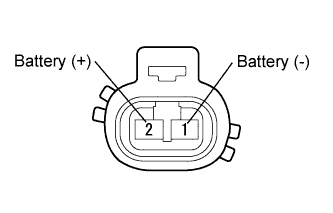
| 9.INSPECT DOOR MIRROR TURN SIGNAL LIGHT |
Remove the door mirror turn signal light.
Connect the positive (+) lead from the battery to terminal 1 and the negative (-) lead to terminal 2, and then check that the light comes on.
- OK:
- Light comes on.
| | REPLACE DOOR MIRROR TURN SIGNAL LIGHT |
|
|
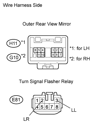
| 10.CHECK WIRE HARNESS (OUTER REAR VIEW MIRROR - TURN SIGNAL FLASHER RELAY) |
Disconnect the H11 (for LH) and G10 (for RH) outer rear view mirror connectors.
Disconnect the E81 turn signal flasher relay connector.
Measure the resistance of the wire harness side connectors.
- Standard resistance:
for LH side:Tester Connection
| Specified Condition
|
E81-3 (LL) - H11-10
| Below 1 Ω
|
E81-3 (LL) or H11-10 - Body ground
| 10 kΩ or higher
|
H11-11 - Body ground
| Below 1 Ω
|
for RH side:Tester Connection
| Specified Condition
|
E81-2 (LR) - G10-10
| Below 1 Ω
|
E81-2 (LR) or G10-10 - Body ground
| 10 kΩ or higher
|
G10-11 - Body ground
| Below 1 Ω
|
| | REPAIR OR REPLACE HARNESS AND CONNECTOR |
|
|
| OK |
|
|
|
| REPLACE OUTER REAR VIEW MIRROR |
|
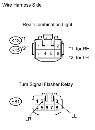
| 11.INSPECT REAR COMBINATION LIGHT |
Remove the rear combination light.
Connect the positive (+) lead from the battery to terminal 5 and the negative (-) lead to terminal 1, then check that the bulb illuminates.
- HINT:
- Be sure to check the bulb first.
- OK:
- Bulb illuminates.
| | REPLACE REAR COMBINATION LIGHT |
|
|
| 12.CHECK WIRE HARNESS (TURN SIGNAL FLASHER RELAY - REAR COMBINATION LIGHT) |
Disconnect the K13 (for RH) and K15 (for LH) rear combination light connectors.
Disconnect the E81 turn signal flasher relay connector.
Measure the resistance of the wire harness side connectors.
- Standard resistance:
for LH side:Tester Connection
| Specified Condition
|
E81-3 (LL) - K15-5
| Below 1 Ω
|
E81-3 (LL) or K15-5 - Body ground
| 10 kΩ or higher
|
for RH side:Tester Connection
| Specified Condition
|
E81-2 (LR) - K13-5
| Below 1 Ω
|
E81-2 (LR) or K13-5 - Body ground
| 10 kΩ or higher
|
| | REPAIR OR REPLACE HARNESS AND CONNECTOR |
|
|
| OK |
|
|
|
| REPAIR OR REPLACE HARNESS AND CONNECTOR (REAR COMBINATION LIGHT - BODY GROUND) |
|
| 13.CHECK OPERATION OF TURN SIGNAL LIGHT |
When the turn signal light switch is operated, check that the appropriate turn signal light flashes.
ResultCondition
| Proceed to
|
All lights do not flash
| A
|
Front turn signal light (LH or RH) does not flash
| B
|
Front side turn signal light (LH or RH) does not flash*1
| C
|
Rear turn signal light (LH or RH) does not flash
| D
|
Door mirror turn signal light (LH or RH) does not flash*2
| E
|
*1: w/o Door Mirror Turn Signal Light
*2: w/ Door Mirror Turn Signal Light
| 14.INSPECT FUSE (ECU-IG2, HAZ) |
Remove the ECU-IG2 fuse from the instrument panel junction block.
Remove the HAZ fuse from the engine room No. 1 relay block.
Measure the resistance of the fuse.
- Standard resistance:
- Below 1 Ω
| 15.CHECK WIRE HARNESS (TURN SIGNAL FLASHER RELAY - BATTERY) |
Remove the turn signal flasher relay from the instrument panel junction block.
Measure the voltage of the relay block.
- Standard voltage:
Tester Connection
| Condition
| Specified Condition
|
Turn signal flasher relay terminal 1 (IG) - Body ground
| Ignition switch on (IG)
| 11 to 14 V
|
Turn signal flasher relay terminal 4 (+B) - Body ground
| Always
| 11 to 14 V
|
| | REPAIR OR REPLACE HARNESS AND CONNECTOR |
|
|
| 16.INSPECT HEADLIGHT DIMMER SWITCH |
Remove the headlight dimmer switch.
Measure the resistance of the switch.
- Standard resistance:
Tester Connection
| Condition
| Specified Condition
|
13 (TR) - 12 (EL)
| Right turn
| Below 1 Ω
|
15 (TL) - 12 (EL)
| Left turn
| Below 1 Ω
|
13 (TR) - 12 (EL)
| Neutral
| 10 kΩ or higher
|
15 (TL) - 12 (EL)
| Neutral
| 10 kΩ or higher
|
| | REPLACE HEADLIGHT DIMMER SWITCH ASSEMBLY |
|
|
| 17.CHECK WIRE HARNESS (TURN SIGNAL FLASHER RELAY - DIMMER SWITCH) |
Remove the turn signal flasher relay from the instrument panel junction block.
Disconnect the E15 headlight dimmer switch connector.
Measure the resistance of the wire harness side connectors and junction block.
Tester Connection
| Specified Condition
|
Turn signal flasher relay terminal 5 (EL) - E15-15 (TL)
| Below 1 Ω
|
Turn signal flasher relay terminal 5 (EL) or E15-15 (TL) - Body ground
| 10 kΩ or higher
|
Turn signal flasher relay terminal 6 (ER) - E15-13 (TR)
| Below 1 Ω
|
Turn signal flasher relay terminal 6 (ER) or E15-13 (TR) - Body ground
| 10 kΩ or higher
|
E15-12 (EL) - Body ground
| Below 1 Ω
|
| | REPAIR OR REPLACE HARNESS AND CONNECTOR |
|
|
| OK |
|
|
|
| REPLACE TURN SIGNAL FLASHER RELAY |
|
| 18.INSPECT FRONT TURN SIGNAL LIGHT BULB |
Remove the front turn signal light bulb.
Connect the positive (+) lead from the battery to terminal 2 and the negative (-) lead to terminal 1, then check that the bulb illuminates.
- OK:
- Bulb illuminates.
| | REPLACE FRONT TURN SIGNAL LIGHT BULB |
|
|
| 19.CHECK WIRE HARNESS (INSTRUMENT PANEL JUNCTION BLOCK - FRONT TURN SIGNAL LIGHT) |
Remove the turn signal flasher relay.
Disconnect the A16 (for LH) and A37 (for RH) front turn signal light connectors.
Measure the resistance of the wire harness side connectors.
- Standard resistance:
for LH side:Tester Connection
| Specified Condition
|
Junction block turn signal flasher relay terminal 3 (LL) - A16-2
| Below 1 Ω
|
Junction block turn signal flasher relay terminal 3 (LL) or A16-2 - Body ground
| 10 kΩ or higher
|
for RH side:Tester Connection
| Specified Condition
|
Junction block turn signal flasher relay terminal 2 (LR) - A37-2
| Below 1 Ω
|
Junction block turn signal flasher relay terminal 2 (LR) or A37-2 - Body ground
| 10 kΩ or higher
|
| | REPAIR OR REPLACE HARNESS AND CONNECTOR |
|
|
| OK |
|
|
|
| REPAIR OR REPLACE HARNESS AND CONNECTOR (FRONT TURN SIGNAL LIGHT - BODY GROUND) |
|
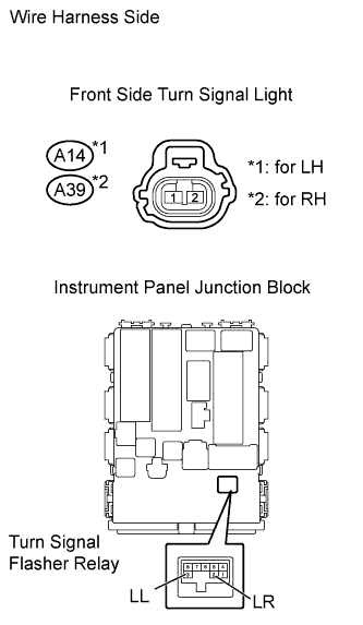
| 20.INSPECT FRONT SIDE TURN SIGNAL LIGHT BULB |
Remove the front side turn signal light bulb.
Connect the positive (+) lead from the battery to terminal 2 and the negative (-) lead to terminal 1, then check that the bulb illuminates.
- OK:
- Bulb illuminates.
| | REPLACE FRONT SIDE TURN SIGNAL LIGHT BULB |
|
|
| 21.CHECK WIRE HARNESS (JUNCTION BLOCK - FRONT SIDE TURN SIGNAL LIGHT) |
Disconnect the A14 (for LH) and A39 (for RH) front side turn signal light connectors.
Remove the turn signal flasher relay.
Measure the resistance of the wire harness side connectors.
- Standard resistance:
for LH side:Tester Connection
| Specified Condition
|
Junction block turn signal flasher relay terminal 3 (LL) - A14-2
| Below 1 Ω
|
Junction block turn signal flasher relay terminal 3 (LL) or A14-2 - Body ground
| 10 kΩ or higher
|
for RH side:Tester Connection
| Specified Condition
|
Junction block turn signal flasher relay terminal 2 (LR) - A39-2
| Below 1 Ω
|
Junction block turn signal flasher relay terminal 2 (LR) or A39-2 - Body ground
| 10 kΩ or higher
|
| | REPAIR OR REPLACE HARNESS AND CONNECTOR |
|
|
| OK |
|
|
|
| REPAIR OR REPLACE HARNESS AND CONNECTOR (FRONT SIDE TURN SIGNAL LIGHT - BODY GROUND) |
|
| 22.INSPECT REAR COMBINATION LIGHT |
Remove the rear combination light.
Connect the positive (+) lead from the battery to terminal 5 and the negative (-) lead to terminal 1, then check that the bulb illuminates.
- HINT:
- Be sure to check the bulb first.
- OK:
- Bulb illuminates.
| | REPLACE REAR COMBINATION LIGHT |
|
|
| 23.CHECK WIRE HARNESS (INSTRUMENT PANEL JUNCTION BLOCK - REAR COMBINATION LIGHT) |
Disconnect the K13 (for RH) and K15 (for LH) rear combination light connectors.
Remove the turn signal flasher relay.
Measure the resistance of the wire harness side connectors.
- Standard resistance:
for LH side:Tester Connection
| Specified Condition
|
Junction block turn signal flasher relay terminal 3 (LL) - K15-5
| Below 1 Ω
|
Junction block turn signal flasher relay terminal 3 (LL) or K15-5 - Body ground
| 10 kΩ or higher
|
for RH side:Tester Connection
| Specified Condition
|
Junction block turn signal flasher relay terminal 2 (LR) - K13-5
| Below 1 Ω
|
Junction block turn signal flasher relay terminal 2 (LR) or K13-5 - Body ground
| 10 kΩ or higher
|
| | REPAIR OR REPLACE HARNESS AND CONNECTOR |
|
|
| OK |
|
|
|
| REPAIR OR REPLACE HARNESS AND CONNECTOR (REAR COMBINATION LIGHT - BODY GROUND) |
|
| 24.INSPECT DOOR MIRROR TURN SIGNAL LIGHT |
Remove the door mirror turn signal light.
Connect the positive (+) lead from the battery to terminal 1 and the negative (-) lead to terminal 2, and then check that the light comes on.
- OK:
- Light comes on.
| | REPLACE DOOR MIRROR TURN SIGNAL LIGHT |
|
|
| 25.CHECK WIRE HARNESS (INSTRUMENT PANEL JUNCTION BLOCK - OUTER REAR VIEW MIRROR) |
Disconnect the H11 (for LH) and G10 (for RH) outer rear view mirror connectors.
Remove the turn signal flasher relay.
Measure the resistance of the wire harness side connectors.
- Standard resistance:
for LH side:Tester Connection
| Specified Condition
|
Junction block turn signal flasher relay terminal 3 (LL) - H11-10
| Below 1 Ω
|
Junction block turn signal flasher relay terminal 3 (LL) or H11-10 - Body ground
| 10 kΩ or higher
|
H11-11 - Body ground
| Below 1 Ω
|
for RH side:Tester Connection
| Specified Condition
|
Junction block turn signal flasher relay terminal 2 (LR) - G10-10
| Below 1 Ω
|
Junction block turn signal flasher relay terminal 2 (LR) or G10-10 - Body ground
| 10 kΩ or higher
|
G10-11 - Body ground
| Below 1 Ω
|
| | REPAIR OR REPLACE HARNESS AND CONNECTOR |
|
|
| OK |
|
|
|
| REPLACE OUTER REAR VIEW MIRROR |
|
| 26.INSPECT FRONT SIDE TURN SIGNAL LIGHT BULB |
Remove the front side turn signal light bulb.
Connect the positive (+) lead from the battery to terminal 2 and the negative (-) lead to terminal 1, then check that the bulb illuminates.
- OK:
- Bulb illuminates.
| | REPLACE FRONT SIDE TURN SIGNAL LIGHT BULB |
|
|
| 27.CHECK WIRE HARNESS (TURN SIGNAL FLASHER RELAY - FRONT SIDE TURN SIGNAL LIGHT) |
Disconnect the A14 (for LH) and A39 (for RH) front side turn signal light connectors.
Disconnect the E81 turn signal flasher relay connector.
Measure the resistance of the wire harness side connectors.
- Standard resistance:
for LH side:Tester Connection
| Specified Condition
|
E81-3 (LL) - A14-2
| Below 1 Ω
|
E81-3 (LL) or A14-2 - Body ground
| 10 kΩ or higher
|
for RH side:Tester Connection
| Specified Condition
|
E81-2 (LR) - A39-2
| Below 1 Ω
|
E81-2 (LR) or A39-2 - Body ground
| 10 kΩ or higher
|
| | REPAIR OR REPLACE HARNESS AND CONNECTOR |
|
|
| OK |
|
|
|
| REPAIR OR REPLACE HARNESS AND CONNECTOR (FRONT SIDE TURN SIGNAL LIGHT - BODY GROUND) |
|