Dtc C1297/97 Steering Angle Sensor
Drive Line. Toyota Rav4. Aca30, 33, 38 Gsa33 Zsa30, 35
DESCRIPTION
WIRING DIAGRAM
INSPECTION PROCEDURE
CHECK FOR DTC
CHECK WIRE HARNESS (STEERING ANGLE SENSOR - BATTERY)
CHECK WIRE HARNESS (STEERING ANGLE SENSOR - BODY GROUND)
DTC C1297/97 Steering Angle Sensor |
DESCRIPTION
- The 4WD control ECU determines that the vehicle is turning based on the signals sent from the steering angle sensor.
- The steering angle sensor signal is sent to the 4WD control ECU via the CAN communication system.
- The 4WD control ECU detects the amount of steering wheel movement and performs "slip control at vehicle start up", according to the amount of movement, and "slip control" to secure high turning performance.
DTC No.
| DTC Detection Condition
| Trouble Area
|
C1297/97
| When voltage of 4WD control ECU IG1 terminal is 9.5 V or more, and steering angle sensor malfunction signal is received.
| - Steering angle sensor
- CAN communication
- 4WD control ECU
- Wire harness
|
WIRING DIAGRAM
INSPECTION PROCEDURE
- HINT:
- Check the condition of each related circuit connector before troubleshooting (RAV4_ACA30 RM000000UZ306OX.html).
Clear the DTC (RAV4_ACA30 RM0000020BA00VX.html).
Turn the ignition switch off.
Turn the ignition switch on (IG) again and check that no CAN communication system DTC(s) is output.
Start the engine.
Drive the vehicle and turn the steering wheel to the right and left at a speed of 35 km/h (22 mph) and check that no brake control system (steering angle sensor) DTC (C1432,C1433 or C1434) is output (RAV4_ACA30 RM0000020BA00VX.html).
- Result:
Result
| Proceed to
|
Neither CAN communication system DTC nor brake control system DTC is output
| A
|
CAN communication system DTC is output
| B
|
Brake control system (steering angle sensor) DTC (C1432,C1433 or C1434) is output
| C
|
- HINT:
- When DTCs indicating a CAN communication system malfunction are output, repair the CAN communication system before repairing each corresponding sensor.
| | REPAIR CIRCUIT INDICATOR OUTPUT CODE (CAN COMMUNICATION SYSTEM) |
|
|
| | REPAIR OR REPLACE CIRCUIT INDICATOR OUTPUT CODE (STEERING ANGLE SENSOR CIRCUIT) |
|
|
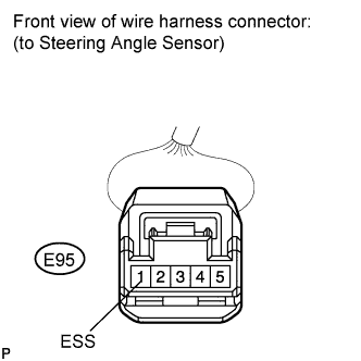
| 2.CHECK WIRE HARNESS (STEERING ANGLE SENSOR - BATTERY) |
Disconnect the E95 sensor connector.
Measure the voltage of the wire harness side connector.
- Standard voltage:
Tester Connection
| Condition
| Specified Condition
|
E95-4 (IG) - Body ground
| Ignition switch on (IG)
| 10 to 14 V
|
E95-5 (BAT) - Body ground
| Always
| 10 to 14 V
|
| | REPAIR OR REPLACE HARNESS AND CONNECTOR |
|
|
| 3.CHECK WIRE HARNESS (STEERING ANGLE SENSOR - BODY GROUND) |
Disconnect the E95 sensor connector.
Measure the resistance of the wire harness side connector.
- Standard resistance:
Tester Connection
| Condition
| Specified Condition
|
E95-1 (ESS) - Body ground
| Always
| Below 1 Ω
|
- Result:
Result
| Proceed to
|
OK (When troubleshooting according to DTC chart)
| A
|
OK (When troubleshooting according to PROBLEM SYMPTOMS TABLE)
| B
|
NG
| C
|
| | PROCEED TO NEXT CIRCUIT INSPECTION SHOWN IN PROBLEM SYMPTOMS TABLE |
|
|
| | REPAIR OR REPLACE HARNESS AND CONNECTOR |
|
|
| A |
|
|
|
| REPLACE STEERING ANGLE SENSOR |
|