Audio And Visual System Speed Signal Circuit
DESCRIPTION
WIRING DIAGRAM
INSPECTION PROCEDURE
CHECK OPERATION OF SPEEDOMETER
CHECK HARNESS AND CONNECTOR (RADIO RECEIVER - COMBINATION METER)
AUDIO AND VISUAL SYSTEM - Speed Signal Circuit |
DESCRIPTION
This circuit sends a speed signal from the combination meter to the radio receiver.
WIRING DIAGRAM
INSPECTION PROCEDURE
| 1.CHECK OPERATION OF SPEEDOMETER |
Drive the vehicle and check if the function of the speedometer on the combination meter is normal.
- OK:
- Actual speed and the speed indicated on the speedometer are the same.
- HINT:
- The vehicle speed sensor is functioning normally when the indication on the speedometer is normal.
| | GO TO METER / GAUGE SYSTEM |
|
|
| 2.CHECK HARNESS AND CONNECTOR (RADIO RECEIVER - COMBINATION METER) |
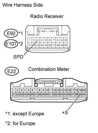
Disconnect the E92*1 or E107*2 radio receiver connector.
*1: except Europe
*2: for Europe
Disconnect the E22 meter connector.
Measure the resistance according to the value(s) in the table below.
- Standard Resistance:
except EuropeTester Connection
| Specified Condition
|
E92-3 (SPD) - E22-39 (+S)
| Below 1 Ω
|
for EuropeTester Connection
| Specified Condition
|
E107-3 (SPD) - E22-39 (+S)
| Below 1 Ω
|
| | REPAIR OR REPLACE HARNESS OR CONNECTOR |
|
|
| OK |
|
|
|
| REPLACE RADIO RECEIVER ASSEMBLY |
|