Power Door Lock Control System Key Lock-In Prevention Function Does Not Work Properly
Door Lock. Toyota Rav4. Aca30, 33, 38 Gsa33 Zsa30, 35
DESCRIPTION
WIRING DIAGRAM
INSPECTION PROCEDURE
READ VALUE USING INTELLIGENT TESTER (UNLOCK WARNING SWITCH)
READ VALUE USING INTELLIGENT TESTER (DRIVER SIDE DOOR COURTESY LIGHT SWITCH)
INSPECT FRONT DOOR COURTESY LIGHT SWITCH ASSEMBLY LH
CHECK WIRE HARNESS (SWITCH - ECU)
INSPECT UNLOCK WARNING SWITCH ASSEMBLY
CHECK WIRE HARNESS (SWITCH - ECU)
POWER DOOR LOCK CONTROL SYSTEM - Key Lock-in Prevention Function does not Work Properly |
DESCRIPTION
When the key is in the ignition key cylinder or the door courtesy light ON signal is output to the main body ECU, performing the door lock operation with the lock switch does not lock the door.
WIRING DIAGRAM
INSPECTION PROCEDURE
| 1.READ VALUE USING INTELLIGENT TESTER (UNLOCK WARNING SWITCH) |
Use the Data List to check if the unlock warning switch is functioning properly.
Main body ECUItem
| Measurement Item / Display (Range)
| Normal Condition
| Diagnostic Note
|
Key Unlock Warning SW
| Unlock warning switch signal / ON or OFF
| ON: Key is in ignition key cylinder
OFF: No key is in ignition key cylinder
| -
|
- OK:
- When the switch is operating, the intelligent tester should display as shown in the table.
| 2.READ VALUE USING INTELLIGENT TESTER (DRIVER SIDE DOOR COURTESY LIGHT SWITCH) |
Use the Data List to check if the door courtesy light switch is functioning properly.
Main body ECUItem
| Measurement Item / Display (Range)
| Normal Condition
| Diagnostic Note
|
D Door Courtesy SW
| Driver side door courtesy light switch signal / ON or OFF
| ON: Driver side door is open
OFF: Driver side door is closed
| -
|
- OK:
- When the switch is operating, the intelligent tester should display as shown in the table.
| | REPLACE INSTRUMENT PANEL JUNCTION BLOCK (MAIN BODY ECU) |
|
|
| 3.INSPECT FRONT DOOR COURTESY LIGHT SWITCH ASSEMBLY LH |
Remove the front door courtesy light switch.
Measure the resistance of the switch.
- Standard resistance:
Tester Connection
| Switch Condition
| Specified Condition
|
1 - Body ground
| Not pushed (ON)
| Below 1 Ω
|
1 - Body ground
| Pushed (OFF)
| 10 kΩ or higher
|
| | REPLACE FRONT DOOR COURTESY LIGHT SWITCH ASSEMBLY LH |
|
|
| 4.CHECK WIRE HARNESS (SWITCH - ECU) |
for LHD:
Disconnect the K8 switch connector.
Disconnect the IA junction block connector.
Measure the resistance of the wire harness side connectors.
- Standard resistance:
Tester Connection
| Specified Condition
|
K8-1 - IA-21 (DCTY)
| Below 1 Ω
|
for RHD:
Disconnect the L4 switch connector.
Disconnect the IC junction block connector.
Measure the resistance of the wire harness side connectors.
- Standard resistance:
Tester Connection
| Specified Condition
|
L4-1 - IC-6 (DCTY)
| Below 1 Ω
|
| | REPAIR OR REPLACE HARNESS AND CONNECTOR |
|
|
| OK |
|
|
|
| REPLACE INSTRUMENT PANEL JUNCTION BLOCK (MAIN BODY ECU) |
|
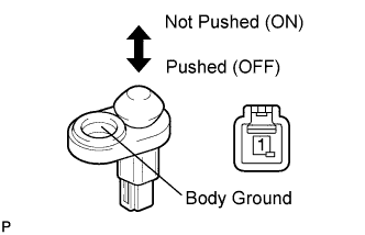
| 5.INSPECT UNLOCK WARNING SWITCH ASSEMBLY |
Remove the unlock warning switch.
Measure the resistance of the switch.
- Standard resistance:
Tester Connection
| Switch Condition
| Specified Condition
|
1- 2
| Not pushed
| 10 kΩ or higher
|
1- 2
| Pushed
| Below 1 Ω
|
| | REPLACE UNLOCK WARNING SWITCH ASSEMBLY |
|
|
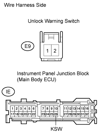
| 6.CHECK WIRE HARNESS (SWITCH - ECU) |
Disconnect the E9 switch connector.
Disconnect the IE junction block connector.
Measure the resistance of the wire harness side connectors.
- Standard resistance:
Tester Connection
| Specified Condition
|
E9-1 - Body ground
| Below 1 Ω
|
E9-1 - IE26 (KSW)
| Below 1 Ω
|
| | REPAIR OR REPLACE HARNESS AND CONNECTOR |
|
|
| OK |
|
|
|
| REPLACE INSTRUMENT PANEL JUNCTION BLOCK (MAIN BODY ECU) |
|