Wireless Door Lock Control System (W/ Entry And Start System) Only Wireless Control Function Is Inoperative
Door Lock. Toyota Rav4. Aca30, 33, 38 Gsa33 Zsa30, 35
DESCRIPTION
WIRING DIAGRAM
INSPECTION PROCEDURE
CHECK POWER DOOR LOCK OPERATION
CHECK ELECTRICAL KEY TRANSMITTER
CHECK ELECTRICAL KEY TRANSMITTER (LED)
INSPECT TRANSMITTER BATTERY (VOLTAGE)
CHECK WAVE ENVIRONMENT
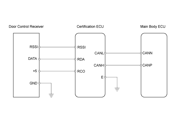
CHECK HARNESS AND CONNECTOR (CERTIFICATION ECU - DOOR CONTROL RECEIVER)
CHECK DOOR CONTROL RECEIVER
WIRELESS DOOR LOCK CONTROL SYSTEM (w/ Entry and Start System) - Only Wireless Control Function is Inoperative |
DESCRIPTION
The door control receiver receives signals from the transmitter and sends these signals to the main body ECU via the certification ECU using the serial line. The main body ECU then controls all doors by sending lock / unlock signals to each door, and sends hazard flasher relay signals to the FLSH relay*1 (turn signal flasher relay*2).- HINT:
- *1: for LHD
- *2: for RHD
WIRING DIAGRAM
INSPECTION PROCEDURE
| 1.CHECK POWER DOOR LOCK OPERATION |
When the door control switch on the master switch assembly is operated, check that the locked doors unlock (RAV4_ACA30 RM000001Y7M006X.html).
- OK:
- Locked doors unlock.
| | GO TO POWER DOOR LOCK CONTROL SYSTEM (PROBLEM SYMPTOMS TABLE) |
|
|
| 2.CHECK ELECTRICAL KEY TRANSMITTER |
When another registered door control transmitter is used, check that the wireless door lock control function operate normally (RAV4_ACA30 RM000001VRW002X.html).
- OK:
- Wireless door lock control function operates normally.
| 3.CHECK ELECTRICAL KEY TRANSMITTER (LED) |
Check that the transmitter LED illuminates 3 times when the switch is pressed 3 times.
- Result:
Result
| Proceed to
|
Transmitter LED does not illuminate at all when switch is pressed 3 times
| A
|
Transmitter LED illuminates each time when switch is pressed 3 times
| B
|
Transmitter LED does not illuminate the second or third time
| C
|
- HINT:
- If the transmitter LED does not illuminate the second or third time, the transmitter battery is depleted.
| | REPLACE ELECTRICAL KEY TRANSMITTER |
|
|
| | REPLACE TRANSMITTER BATTERY |
|
|
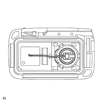
| 4.INSPECT TRANSMITTER BATTERY (VOLTAGE) |
Remove the battery from the electrical key transmitter that does not operate. Attach a lead wire (0.6 mm (0.0236 in.) or less in diameter including wire sheath) with tape or equivalent to the negative terminal.
- NOTICE:
- Do not wrap the lead wire around the terminal; wedge it between the terminals, or solder it. The terminal may be deformed or damaged, and the battery will not be able to be installed correctly.
Carefully pull the lead wire out from the position shown in the illustration and install the previously removed transmitter battery.
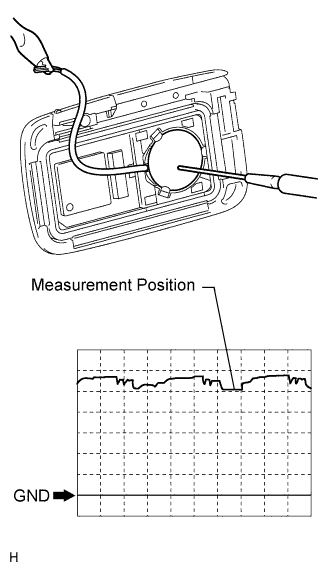
Using an oscilloscope, check the transmitter battery voltage waveform.
- HINT:
- When measuring the battery voltage, while operating the lock switch of a door outside handle, bring the electrical key transmitter within the entry operating range to perform the measurement. For the entry operating range.
- Standard Voltage:
Item
| Content
|
Tester Connection
| Battery positive (+) - Battery negative (-)
|
Tool Setting
| 0.5 V/DIV., 100 ms/DIV.
|
Condition
| Engine switch off, all doors closed, and lock switch pushed
|
Specified Condition
| 2.2 to 3.2 V (Refer to the waveform)
|
| | REPLACE TRANSMITTER BATTERY |
|
|
| OK |
|
|
|
| REPLACE ELECTRICAL KEY TRANSMITTER |
|
Bring the electrical key transmitter near the door control receiver, and perform a wireless and entry operation check.
- HINT:
- When the electrical key transmitter is brought near the door control receiver, the possibility of wave interference decreases, and it can be determined if wave interference is causing the problem symptom.
- If the inspection result is that the problem only occurs in certain locations or times of day, the possibility of wave interference is high. Also, added vehicle components may cause wave interference. If installed, remove them and perform the operation check.
- OK:
- Wireless door lock control function operate normally.
| OK |
|
|
|
| AFFECTED BY WAVE INTERFERENCE |
|
| 6.CHECK HARNESS AND CONNECTOR (CERTIFICATION ECU - DOOR CONTROL RECEIVER) |
Disconnect the E63 ECU connector.
Disconnect the L13 receiver connector.
Measure the resistance of the wire harness side connectors.
- Standard resistance:
Tester Connection
| Condition
| Specified Condition
|
E63-38 (RDA) - L13-5 (DATA)
| Always
| Below 1 Ω
|
E63-39 (RSSI) - L13-2 (RSSI)
|
E63-29 (RCO) - L13-4 (+5)
|
E63-38 (RDA) or L13-5 (DATA) - Body ground
| Always
| 10 kΩ or higher
|
E63-39 (RSSI) or L13-2 (RSSI) - Body ground
|
E63-29 (RCO) or L13-4 (+5) - Body ground
|
| | REPAIR OR REPLACE HARNESS OR CONNECTOR |
|
|
| 7.CHECK DOOR CONTROL RECEIVER |
Temporarily replace the door lock control receiver with a new or normally functioning one.
- for Short Body (RAV4_ACA30 RM000001XXF003X.html).
- for Long Body (RAV4_ACA30 RM0000020MG00AX.html).
Check that the doors can be locked and unlocked by using the transmitter LOCK and UNLOCK switches.
- OK:
- Doors can be locked and unlocked with transmitter.
| | REPLACE ECU AGGREGATION BOX (CERTIFICATION ECU) |
|
|
| OK |
|
|
|
| END (DOOR CONTROL RECEIVER IS DEFECTIVE) |
|