Wiper And Washer System (W/ Rain Sensor) Front Wiper Motor Circuit
DESCRIPTION
WIRING DIAGRAM
INSPECTION PROCEDURE
INSPECT WINDSHIELD WIPER MOTOR ASSEMBLY
CHECK WIRE HARNESS (MOTOR - RELAY AND BODY GROUND)
WIPER AND WASHER SYSTEM (w/ Rain Sensor) - Front Wiper Motor Circuit |
DESCRIPTION
The auto wiper relay controls the front wiper motor.
WIRING DIAGRAM
INSPECTION PROCEDURE
| 1.INSPECT WINDSHIELD WIPER MOTOR ASSEMBLY |
Check windshield wiper motor operation.
Remove the windshield wiper motor (RAV4_ACA30 RM00000114B00EX.html).
Apply battery voltage to the wiper motor connector and check the operation of the wiper motor.
- OK:
for LHDMeasurement Condition
| Specified Condition
|
Battery positive (+) → Terminal 3 (+2)
Battery negative (-) → Terminal 4 (E)
| Motor operates at HI speed
|
Battery positive (+) → Terminal 5 (+1)
Battery negative (-) → Terminal 4 (E)
| Motor operates at LO speed
|
- for RHD:
Measurement Condition
| Specified Condition
|
Battery positive (+) → Terminal 4 (+2)
Battery negative (-) → Terminal 5 (E)
| Motor operates at HI speed
|
Battery positive (+) → Terminal 1 (+1)
Battery negative (-) → Terminal 5 (E)
| Motor operates at LO speed
|
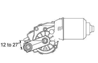
Check automatic stop operation.
Connect the battery's positive (+) lead to terminal 5*1 or 1*2 (+1) and the negative (-) lead to terminal 4*1 or 5*2 (E). With the motor rotating at low speed (LO), disconnect the 5*1 or 1*2 (+1) to stop the wiper motor operation at any position other than the automatic stop position.
Using SST, connect terminals 5 (+1)*1 or 1 (+1)*2 and 1 (B)*1 or 3 (B)*2. Then connect the battery's positive (+) lead to terminal 2 (B) to restart the motor operation at low speed (LO).
Check that the motor stops automatically at the automatic stop position.
- OK:
- Motor stops automatically at the automatic stop position.
| | REPLACE WINDSHIELD WIPER MOTOR ASSEMBLY |
|
|
| 2.CHECK WIRE HARNESS (MOTOR - RELAY AND BODY GROUND) |
Disconnect the A8 motor connector.
Disconnect the E66 relay connector.
Measure the resistance of the wire harness side connectors.
- Standard resistance:
for LHDTester Connection
| Specified Condition
|
A8-5 (+1) - E66-2 (+1)
| Below 1 Ω
|
A8-3 (+2) - E66-3 (+2)
|
A8-1 (+S) - E66-10 (+SM)
|
A8-4 (E) - Body ground
|
- for RHD:
Tester Connection
| Specified Condition
|
A8-1 (+1) - E66-2 (+1)
| Below 1 Ω
|
A8-4 (+2) - E66-3 (+2)
|
A8-3 (+S) - E66-10 (+SM)
|
A8-5 (E) - Body ground
|
| | REPAIR OR REPLACE HARNESS AND CONNECTOR |
|
|
| OK |
|
|
|
| PROCEED TO NEXT CIRCUIT INSPECTION SHOWN IN PROBLEM SYMPTOMS TABLE |
|