Wiper And Washer System (W/ Rain Sensor) Headlight Cleaner Switch Circuit
DESCRIPTION
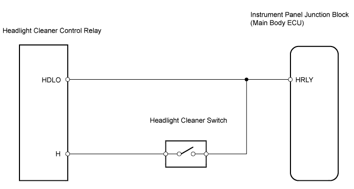
WIRING DIAGRAM
INSPECTION PROCEDURE
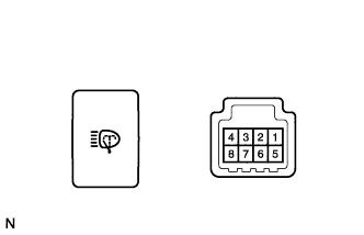
INSPECT HEADLIGHT CLEANER SWITCH
CHECK WIRE HARNESS (SWITCH - ECU AND RELAY)
CHECK WIRE HARNESS (RELAY - ECU)
WIPER AND WASHER SYSTEM (w/ Rain Sensor) - Headlight Cleaner Switch Circuit |
DESCRIPTION
This circuit detects the conditions of the headlight cleaner switch.
WIRING DIAGRAM
INSPECTION PROCEDURE
| 1.INSPECT HEADLIGHT CLEANER SWITCH |
Remove the headlight cleaner switch.
Measure the resistance of the switch.
- Standard resistance:
Tester Connection
| Switch Condition
| Specified Condition
|
5 - 8
| ON
| Below 25 Ω
|
OFF
| 10 kΩ or higher
|
| | REPLACE HEADLIGHT CLEANER SWITCH |
|
|
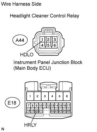
| 2.CHECK WIRE HARNESS (SWITCH - ECU AND RELAY) |
Disconnect the E4 switch connector.
Disconnect the A44 relay connector
Disconnect the E18 ECU connector.
Measure the resistance of the wire harness side connectors.
- Standard resistance:
Tester Connection
| Specified Condition
|
E4-8 - A44-2 (H)
| Below 1 Ω
|
E4-5 - E18-20 (HRLY)
|
| | REPAIR OR REPLACE HARNESS AND CONNECTOR |
|
|
| 3.CHECK WIRE HARNESS (RELAY - ECU) |
Disconnect the A44 relay connector
Disconnect the E18 ECU connector.
Measure the resistance of the wire harness side connectors.
- Standard resistance:
Tester Connection
| Specified Condition
|
A44-1 (HDLO) - E18-20 (HRLY)
| Below 1 Ω
|
| | REPAIR OR REPLACE HARNESS AND CONNECTOR |
|
|
| OK |
|
|
|
| PROCEED TO NEXT CIRCUIT INSPECTION SHOWN IN PROBLEM SYMPTOMS TABLE |
|