Lighting. Toyota Rav4. Aca30, 33, 38 Gsa33 Zsa30, 35
DESCRIPTION
WIRING DIAGRAM
INSPECTION PROCEDURE
CHECK WHETHER LIGHTS ILLUMINATE
INSPECT FUSE (TAIL)
CHECK WIRE HARNESS (INSTRUMENT PANEL JUNCTION BLOCK - BATTERY)
CHECK INSTRUMENT PANEL JUNCTION BLOCK (T-LP RELAY)
CHECK WIRE HARNESS (MAIN BODY ECU - HEADLIGHT DIMMER SWITCH)
CHECK WIRE HARNESS (HEADLIGHT DIMMER SWITCH - BATTERY)
CHECK WIRE HARNESS (HEADLIGHT DIMMER SWITCH - BODY GROUND)
INSPECT HEADLIGHT DIMMER SWITCH
CHECK INSTRUMENT PANEL JUNCTION BLOCK (TAILLIGHT RELAY)
CHECK WIRE HARNESS (INSTRUMENT PANEL JUNCTION BLOCK - FRONT CLEARANCE LIGHT AND BODY GROUND)
CHECK WIRE HARNESS (INSTRUMENT PANEL JUNCTION BLOCK - REAR COMBINATION LIGHT)
CHECK WIRE HARNESS (INSTRUMENT PANEL JUNCTION BLOCK - LICENSE PLATE LIGHT AND BODY GROUND)
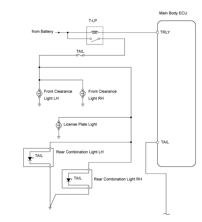
LIGHTING SYSTEM - Taillight Relay Circuit |
DESCRIPTION
When the light control switch, located on the headlight dimmer switch, is turned to the TAIL position, the taillight relay turns on to illuminate the front clearance lights, rear taillights and license plate light.
WIRING DIAGRAM
INSPECTION PROCEDURE
| 1.CHECK WHETHER LIGHTS ILLUMINATE |
Check whether the following lights illuminate: front clearance lights, rear taillights, license plate light.
- Result:
Result
| Proceed to
|
All lights do not illuminate
| A
|
Front clearance lights do not illuminate
| B
|
Rear taillights do not illuminate
| C
|
License plate light does not illuminate
| D
|
All lights illuminate
| E
|
| |
|
| |
|
| |
|
| | PROCEED TO NEXT CIRCUIT INSPECTION SHOWN IN PROBLEM SYMPTOMS TABLE |
|
|
Remove the TAIL fuse from the instrument panel junction block.
Measure the resistance of the fuse.
- Standard resistance:
- Below 1 Ω
| 3.CHECK WIRE HARNESS (INSTRUMENT PANEL JUNCTION BLOCK - BATTERY) |
Disconnect the IG instrument panel junction block connector.
Measure the voltage of the wire harness side connector.
- Standard voltage:
Tester Connection
| Specified Condition
|
IG-1 - Body ground
| 11 to 14 V
|
| | REPAIR OR REPLACE HARNESS AND CONNECTOR |
|
|
| 4.CHECK INSTRUMENT PANEL JUNCTION BLOCK (T-LP RELAY) |
Disconnect the IG, IE and IS instrument panel connectors.
Measure the resistance of the junction block.
- Standard resistance:
Tester Connection
| Specified Condition
|
IG-1 - IE-10
| 10 kΩ or higher
|
IG-1 - IE-10
| Below 1 Ω
(Battery voltage applied to terminals IG-1 and IS-9)
|
| | REPLACE INSTRUMENT PANEL JUNCTION BLOCK (MAIN BODY ECU) |
|
|
| 5.CHECK WIRE HARNESS (MAIN BODY ECU - HEADLIGHT DIMMER SWITCH) |
Disconnect the E18 main body ECU connector.
Disconnect the E15 headlight dimmer switch connector.
Measure the resistance of the wire harness side connectors.
- Standard resistance:
for LH sideTester Connection
| Specified Condition
|
E18-21 (TAIL) - E15-18 (T)
| Below 1 Ω
|
for RH sideTester Connection
| Specified Condition
|
E18-21 (TAIL) - E15-13 (T)
| Below 1 Ω
|
| | REPAIR OR REPLACE HARNESS AND CONNECTOR |
|
|
| 6.CHECK WIRE HARNESS (HEADLIGHT DIMMER SWITCH - BATTERY) |
Connect the E18 main body ECU connector.
Disconnect the E15 headlight dimmer switch connector.
Measure the voltage of the wire harness side connector.
- Standard voltage:
for LH sideTester Connection
| Specified Condition
|
E15-18 (T) - Body ground
| 11 to 14 V
|
for RH sideTester Connection
| Specified Condition
|
E15-13 (T) - Body ground
| 11 to 14 V
|
| | REPLACE INSTRUMENT PANEL JUNCTION BLOCK (MAIN BODY ECU) |
|
|
| 7.CHECK WIRE HARNESS (HEADLIGHT DIMMER SWITCH - BODY GROUND) |
Disconnect the E15 headlight dimmer switch connector.
Measure the resistance of the wire harness side connector.
- Standard resistance:
for LH sideTester Connection
| Specified Condition
|
E15-12 (EL) - Body ground
| Below 1 Ω
|
for RH sideTester Connection
| Specified Condition
|
E15-19 (EL) - Body ground
| Below 1 Ω
|
| | REPAIR OR REPLACE HARNESS AND CONNECTOR |
|
|
| 8.INSPECT HEADLIGHT DIMMER SWITCH |
Remove the headlight dimmer switch.
Measure the resistance of the switch.
- Standard resistance:
for LH sideTester Connection
| Switch Condition
| Specified Condition
|
18 (T) - 12 (EL)
| Light control switch OFF
| 10 kΩ or higher
|
18 (T) - 12 (EL)
| Light control switch TAIL
| Below 1 Ω
|
for RH sideTester Connection
| Switch Condition
| Specified Condition
|
13 (T) - 19 (EL)
| Light control switch OFF
| 10 kΩ or higher
|
13 (T) - 19 (EL)
| Light control switch TAIL
| Below 1 Ω
|
| | REPLACE HEADLIGHT DIMMER SWITCH |
|
|
| OK |
|
|
|
| REPLACE INSTRUMENT PANEL JUNCTION BLOCK (MAIN BODY ECU) |
|
| 9.CHECK INSTRUMENT PANEL JUNCTION BLOCK (TAILLIGHT RELAY) |
Disconnect the IB instrument panel junction block connectors.
Measure the voltage of the junction block.
- Standard voltage:
Tester Connection
| Condition
| Specified Condition
|
Junction block IB terminal 15 - Body ground
| Light control switch TAIL
| 11 to 14 V
|
Junction block IB terminal 33 - Body ground
|
| | REPLACE INSTRUMENT PANEL JUNCTION BLOCK (MAIN BODY ECU) |
|
|
| 10.CHECK WIRE HARNESS (INSTRUMENT PANEL JUNCTION BLOCK - FRONT CLEARANCE LIGHT AND BODY GROUND) |
w/ Hood Moulding:
Disconnect the A75 and A76 front clearance light connectors.
Measure the voltage and resistance of the wire harness side connectors.
- Standard voltage:
Tester Connection
| Condition
| Specified Condition
|
A75-2 - Body ground
| Light control switch TAIL
| 11 to 14 V
|
A76-2 - Body ground
| Light control switch TAIL
| 11 to 14 V
|
- Standard resistance:
Tester Connection
| Specified Condition
|
A75-1 - Body ground
| Below 1 Ω
|
A76-1 - Body ground
| Below 1 Ω
|
w/o Hood Moulding:
Disconnect the A20 and A33 front clearance light connectors.
Measure the voltage and resistance of the wire harness side connectors.
- Standard voltage:
Tester Connection
| Condition
| Specified Condition
|
A20-2 - Body ground
| Light control switch TAIL
| 11 to 14 V
|
A33-2 - Body ground
| Light control switch TAIL
| 11 to 14 V
|
- Standard resistance:
Tester Connection
| Specified Condition
|
A20-1 - Body ground
| Below 1 Ω
|
A33-1 - Body ground
| Below 1 Ω
|
| | REPAIR OR REPLACE HARNESS AND CONNECTOR |
|
|
| OK |
|
|
|
| REPLACE FRONT CLEARANCE LIGHT BULB |
|
| 11.CHECK WIRE HARNESS (INSTRUMENT PANEL JUNCTION BLOCK - REAR COMBINATION LIGHT) |
Disconnect the K13 and K15 rear combination light connectors.
Measure the voltage and resistance of the wire harness side connectors.
- Standard voltage:
Tester Connection
| Condition
| Specified Condition
|
K15-2 - Body ground
| Light control switch TAIL
| 11 to 14 V
|
K13-2 - Body ground
| Light control switch TAIL
| 11 to 14 V
|
- Standard resistance:
Tester Connection
| Specified Condition
|
K15-1 - Body ground
| Below 1 Ω
|
K13-1 - Body ground
| Below 1 Ω
|
| | REPAIR OR REPLACE HARNESS AND CONNECTOR |
|
|
| OK |
|
|
|
| REPLACE REAR COMBINATION LIGHT |
|
| 12.CHECK WIRE HARNESS (INSTRUMENT PANEL JUNCTION BLOCK - LICENSE PLATE LIGHT AND BODY GROUND) |
w/o Tire Carrier:
Disconnect the S6 license plate light connector.
Measure the voltage and resistance of the wire harness side connector.
- Standard voltage:
Tester Connection
| Condition
| Specified Condition
|
S6-1 - Body ground
| Light control switch TAIL
| 11 to 14 V
|
- Standard resistance:
Tester Connection
| Specified Condition
|
S6-2 - Body ground
| Below 1 Ω
|
w/o Rear Fog Light (One Piece Type):
Disconnect the S6 license plate light connector.
Measure the voltage and resistance of the wire harness side connector.
- Standard voltage:
Tester Connection
| Condition
| Specified Condition
|
S6-2 - Body ground
| Light control switch TAIL
| 11 to 14 V
|
- Standard resistance:
Tester Connection
| Specified Condition
|
S6-1 - Body ground
| Below 1 Ω
|
w/o Rear Fog Light (Two Piece Type):
Disconnect the N3 license plate light connector.
Measure the voltage and resistance of the wire harness side connector.
- Standard voltage:
Tester Connection
| Condition
| Specified Condition
|
N3-2 - Body ground
| Light control switch TAIL
| 11 to 14 V
|
- Standard resistance:
Tester Connection
| Specified Condition
|
N3-1 - Body ground
| Below 1 Ω
|
w/ Tire Carrier (w/ Rear Fog Light):
Disconnect the N2 license plate light connector.
Measure the voltage and resistance of the wire harness side connector.
- Standard voltage:
Tester Connection
| Condition
| Specified Condition
|
N2-2 - Body ground
| Light control switch TAIL
| 11 to 14 V
|
- Standard resistance:
Tester Connection
| Specified Condition
|
N2-1 - Body ground
| Below 1 Ω
|
| | REPAIR OR REPLACE HARNESS AND CONNECTOR |
|
|
| OK |
|
|
|
| REPLACE LICENSE PLATE LIGHT BULB |
|