Brake Pedal -- Installation |
| 1. INSTALL BRAKE PEDAL SUPPORT ASSEMBLY |
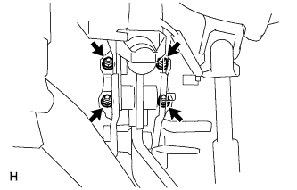 |
Install the support with the 4 nuts.
- Torque:
- 12.7 N*m{130 kgf*cm, 9 ft.*lbf}
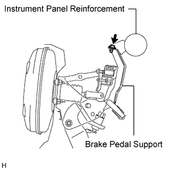
Install the bolt to the support.
- Torque:
- 24 N*m{245 kgf*cm, 18 ft.*lbf}
 |
| 2. INSTALL PUSH ROD PIN |
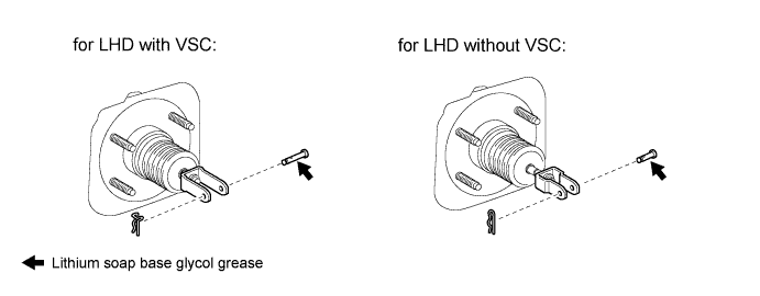
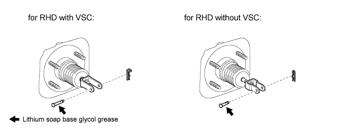
Apply lithium soap base glycol grease to the push rod pin.
Install the push rod pin to the push rod clevis.
- NOTICE:
- The push rod pin must be installed as shown in the illustration.
Install a new clip to the push rod pin.
- NOTICE:
- The clip must be installed as shown in the illustration.
| 3. INSTALL STOP LIGHT SWITCH ASSEMBLY |
Insert the switch into the adjuster until the switch body touches the pedal.
- NOTICE:
- Do not depress the pedal.
 |
Turn the switch a quarter turn clockwise.
- Torque:
- 1.5 N*m{15 kgf*cm, 13 in.*lbf} or less
- NOTICE:
- Do not depress the pedal.
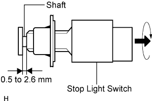 |
Check the switch clearance.
- Standard stop light switch clearance:
- 0.5 to 2.6 mm (0.020 to 0.102 in.)
| 4. CONNECT CONNECTORS |
with VSC:
Connect the brake pedal load sensing switch connector.
Connect the stop light switch connector.
| 5. CHECK AND ADJUST BRAKE PEDAL HEIGHT |
Check the pedal height.
- Standard pedal height from dash panel:
Item Specified Condition for LHD 184.2 to 194.2 mm (7.252 to 7.646 in.) for RHD 168.6 to 178.6 mm (6.638 to 7.031 in.)
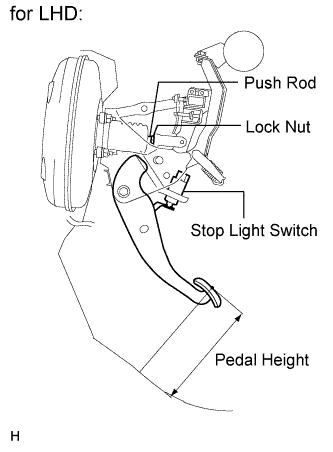 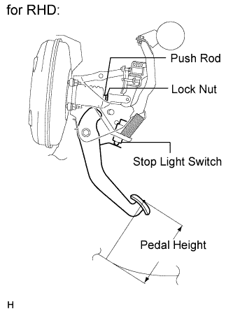 |
Adjust the pedal height.
Disconnect the connector from the stop light switch.
Remove the switch.
Loosen the push rod clevis lock nut.
Adjust the pedal height by turning the push rod.
Tighten the lock nut.
- Torque:
- 26 N*m{265 kgf*cm, 19 ft.*lbf}
Insert the switch into the adjuster until the switch body touches the pedal.
- NOTICE:
- Do not depress the pedal.
Turn the switch a quarter turn clockwise.
- Torque:
- 1.5 N*m{15 kgf*cm, 13 in.*lbf} or less
- NOTICE:
- Do not depress the pedal.
Connect the connector to the switch.
Check the switch clearance.
- Standard stop light switch clearance:
- 0.5 to 2.6 mm (0.020 to 0.102 in.)
| 6. CHECK BRAKE PEDAL FREE PLAY |
Stop the engine. Depress the pedal several times until there is no vacuum in the booster. Then release the pedal.
 |
Depress the pedal until resistance is felt.
Check the pedal free play by measuring the distance between the position in the previous step and the pedal's released position.
- Standard pedal free play:
- 1.0 to 6.0 mm (0.039 to 0.236 in.)
If the free play is as specified, proceed to the "CHECK BRAKE PEDAL RESERVE DISTANCE" procedure.
Check the switch clearance.
- Standard stop light switch clearance:
- 0.5 to 2.6 mm (0.020 to 0.102 in.)
If the clearance is as specified, troubleshoot the brake system and proceed to the "CHECK BRAKE PEDAL RESERVE DISTANCE" procedure.
| 7. CHECK BRAKE PEDAL RESERVE DISTANCE |
Release the parking brake lever. Start the engine.
Depress the pedal and check the pedal reserve distance.
Depress the pedal with a force of 490 N (50 kgf, 110 lbf).
Measure the distance between the pedal and dash panel.
- Standard pedal reserve distance:
Engine VSC LHD RHD 1AZ-FE w/o More than 90 mm (3.54 in.) More than 80 mm (3.15 in.) w/ More than 115 mm (4.53 in.) More than 105 mm (4.13 in.) 2AZ-FE w/o More than 95 mm (3.74 in.) More than 85 mm (3.34 in.) w/ More than 120 mm (4.72 in.) More than 110 mm (4.32 in.) 2GR-FE w/ - More than 110 mm (4.32 in.) 3ZR-FAE w/o More than 75 mm (2.95 in.) More than 70 mm (2.76 in.) w/ More than 110 mm (4.33 in.) More than 100 mm (3.94 in.)
| 8. INSTALL INSTRUMENT PANEL SUB-ASSEMBLY |
Install the instrument panel (RAV4_ACA30 RM000001RHG00HX.html).
| 9. CONNECT CABLE TO NEGATIVE BATTERY TERMINAL |