Dtc B1451/51 Compressor Solenoid Circuit
DESCRIPTION
WIRING DIAGRAM
INSPECTION PROCEDURE
READ VALUE USING INTELLIGENT TESTER (REG CTRL CURRNT)
INSPECT A/C COMPRESSOR
CHECK WIRE HARNESS (A/C COMPRESSOR - AIR CONDITIONING AMPLIFIER)
CHECK WIRE HARNESS (A/C COMPRESSOR - BODY GROUND)
DTC B1451/51 Compressor Solenoid Circuit |
DESCRIPTION
In this circuit, the compressor receives a refrigerant compression demand signal from the air conditioning amplifier. Based on this signal, the compressor changes the degree of refrigerant compression.DTC No.
| DTC Detection Condition
| Trouble Area
|
B1451/51
| Open or short in solenoid of externally changeable compressor circuit
| - A/C compressor*
- Harness and connector between air conditioning amplifier and A/C compressor*
- Air conditioning amplifier
|
- HINT:
- *: Compressor and pulley for except 2GR-FE, compressor and magnetic clutch for 2GR-FE
WIRING DIAGRAM
INSPECTION PROCEDURE
| 1.READ VALUE USING INTELLIGENT TESTER (REG CTRL CURRNT) |
Connect the intelligent tester to the DLC3.
Turn the ignition switch on (IG) and turn the intelligent tester main switch ON.
Select the items below in the DATA LIST, and read the value displayed on the intelligent tester.
- Air conditioning amplifier:
Item
| Measurement Item / Display (Range)
| Normal Condition
| Diagnostic Note
|
Regulator Control Current
| Regulator control current /
Min.: 0 A
Max.: 0.997 A
| Value changes between 0 A and 0.997 A in accordance with A/C compressor operation
| -
|
- OK:
- The display is as specified in the normal condition column.
- Result:
Result
| Proceed to
|
NG
| A
|
OK (Checking from the PROBLEM SYMPTOMS TABLE)
| B
|
OK (Checking from the DTC)
| C
|
| | PROCEED TO NEXT CIRCUIT INSPECTION SHOWN IN PROBLEM SYMPTOMS TABLE |
|
|
| | REPLACE AIR CONDITIONING AMPLIFIER |
|
|
Disconnect the A/C compressor connector.
Measure the resistance of the connector.
- Standard resistance:
Tester Connection
| Condition
| Specified Condition
|
1 (SOL-) - 2 (SOL+)
| 25°C (77°F)
| 10.1 to 11.1 Ω
|
| 3.CHECK WIRE HARNESS (A/C COMPRESSOR - AIR CONDITIONING AMPLIFIER) |
Disconnect the B23 or B40 A/C compressor connector.
Disconnect the E42 amplifier connector.
Measure the resistance of the wire harness side connectors.
- Standard resistance:
Tester Connection
| Specified Condition
|
B23-2 (SOL+) - E42-13 (SOL+) (*1)
| Below 1 Ω
|
B23-2 (SOL+) - Body ground (*1)
| 1 MΩ or higher
|
B40-2 (SOL+) - E42-13 (SOL+) (*2)
| Below 1 Ω
|
B40-2 (SOL+) - Body ground (*2)
| 1 MΩ or higher
|
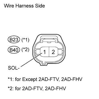
*1: for Except 2AD-FTV, 2AD-FHV
*2: for 2AD-FTV, 2AD-FHV
| | REPAIR OR REPLACE HARNESS OR CONNECTOR |
|
|
| 4.CHECK WIRE HARNESS (A/C COMPRESSOR - BODY GROUND) |
Disconnect the B23 or B40 A/C compressor connector.
Measure the resistance of the wire harness side connector.
- Standard resistance:
Tester Connection
| Specified Condition
|
B23-1 (SOL-) - Body ground (*1)
| Below 1 Ω
|
B40-1 (SOL-) - Body ground (*2)
| Below 1 Ω
|
*1: for Except 2AD-FTV, 2AD-FHV
*2: for 2AD-FTV, 2AD-FHV
| | REPAIR OR REPLACE HARNESS OR CONNECTOR |
|
|
| OK |
|
|
|
| REPLACE AIR CONDITIONING AMPLIFIER |
|