Starter (For 1.6 Kw Type) -- Inspection |
| 1. INSPECT STARTER ASSEMBLY |
- NOTICE:
- These tests must be performed within 3 to 5 seconds to avoid burning out the coil.
Perform the pull-in test.
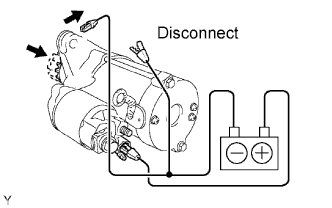
Disconnect the lead wire from terminal C.
Connect the battery to the magnetic switch as shown in the illustration. Check that the clutch pinion gear extends.
If the clutch pinion gear does not move, replace the magnetic switch.

Perform the hold-in test.
Maintain the battery connections of the pull-in test above, but disconnect the negative (-) lead from terminal C. Check that the pinion gear remains extended.
If the clutch pinion gear returns inward, replace the magnetic switch.
 |
Check the clutch pinion gear return.
Disconnect the negative (-) lead from the switch body. Check that the clutch pinion gear returns.
If the clutch pinion gear does not return, replace the magnetic switch.
 |
Perform the no-load performance test.
Connect the lead wire to terminal C. Make sure that the lead is not grounded.
Clamp the starter in a vise.
Connect the battery and an ammeter to the starter as shown in the illustration.
Check that the starter rotates smoothly and steadily while the pinion gear is moving out. Then measure the current.
- Standard current:
- 90 A or less at 11.5 V
 |
| 2. INSPECT MAGNETIC SWITCH ASSEMBLY |
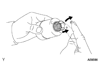
Check the plunger.
Push in the plunger and check that it returns quickly to its original position.
If necessary, replace the magnetic switch assembly.
 |
Check if the pull-in coil has an open circuit.
Measure the resistance between terminals 50 and C.
- Standard resistance:
- Below 1 Ω
 |
Check if the hold-in coil has an open circuit.
Measure the resistance between terminal 50 and the switch body.
- Standard resistance:
- Below 2 Ω
 |
| 3. INSPECT STARTER ARMATURE ASSEMBLY |
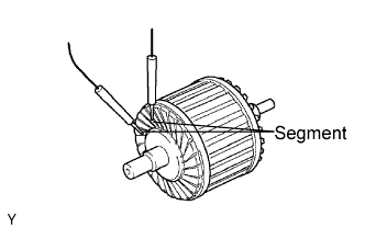
Check if the commutator has an open circuit.
Check the resistance between the segments of the commutator.
- Standard resistance:
- Below 1 Ω
 |
Check if the commutator is grounded.
Measure the resistance between the commutator and armature coil core.
- Standard resistance:
- 10 kΩ or higher
 |
Check the commutator for contamination and burns on its surface.
If the surface is dirty or burnt, correct it with sandpaper (No. 400) or a lathe.
Using a vernier caliper, measure the commutator's length.
- Standard length:
- 3.1 to 3.8 mm (0.122 to 0.150 in.)
 |
| 4. INSPECT STARTER COMMUTATOR END FRAME ASSEMBLY |
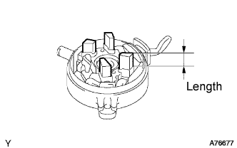
Using a vernier caliper, measure the brush length.
- Standard length:
- 4.0 to 9.0 mm (0.158 to 0.359 in.)
 |
Check the brush insulation.
Measure the resistance between the positive (+) and negative (-) brush.
- Standard resistance:
- 10 kΩ or higher
 |
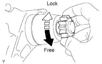
| 5. INSPECT STARTER CLUTCH |
Check the starter clutch.
Rotate the clutch pinion gear counterclockwise and check that it turns freely. Try to rotate the clutch pinion gear clockwise and check that it locks.
If necessary, replace the starter drive housing assembly.
 |