Cruise Control System Tc And Cg Terminal Circuit
DESCRIPTION
WIRING DIAGRAM
INSPECTION PROCEDURE
CHECK WIRE HARNESS (DLC3 - ECM AND BODY GROUND)
CRUISE CONTROL SYSTEM - TC and CG Terminal Circuit |
DESCRIPTION
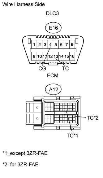
Connecting terminals 13 (TC) and 4 (CG) of the DLC3 enables DTCs to be read through blinking patterns of the combination meter's CRUISE main indicator light.- HINT:
- When a warning light of the combination meter blinks continuously, terminal 13 (TC) of the DLC3 or the ECM may have a ground short.
WIRING DIAGRAM
INSPECTION PROCEDURE
| 1.CHECK WIRE HARNESS (DLC3 - ECM AND BODY GROUND) |
Disconnect the E16 DLC3 connector.
Disconnect the A12 ECM connector.
Measure the resistance of the wire harness side connectors.
- Standard resistance:
except 3ZR-FAETester Connection
| Specified Condition
|
E16-13 (TC) - A12-27 (TC)
| Below 1 Ω
|
E16-4 (CG) - Body ground
|
for 3ZR-FAETester Connection
| Specified Condition
|
E16-13 (TC) - A12-41 (TC)
| Below 1 Ω
|
E16-4 (CG) - Body ground
|
| | REPAIR OR REPLACE HARNESS OR CONNECTOR |
|
|