Dtc P0335 Crankshaft Position Sensor A Circuit
Engine. Toyota Rav4. Aca30, 33, 38 Gsa33 Zsa30, 35
DESCRIPTION
WIRING DIAGRAM
INSPECTION PROCEDURE
READ VALUE USING INTELLIGENT TESTER (ENGINE SPEED)
INSPECT CRANKSHAFT POSITION SENSOR (RESISTANCE)
CHECK HARNESS AND CONNECTOR (CRANKSHAFT POSITION SENSOR - ECM)
CHECK SENSOR INSTALLATION (CRANKSHAFT POSITION SENSOR)
CHECK CRANKSHAFT POSITION SENSOR PLATE (TEETH OF SENSOR PLATE)
REPLACE CRANKSHAFT POSITION SENSOR
CHECK WHETHER DTC OUTPUT RECURS
DTC P0335 Crankshaft Position Sensor "A" Circuit |
DTC P0339 Crankshaft Position Sensor "A" Circuit Intermittent |
DESCRIPTION
The Crankshaft Position (CKP) sensor system consists of a CKP sensor plate and a pickup coil. The sensor plate has 34 teeth and is installed on the crankshaft. The pickup coil is made of wound copper wire, an iron core and magnet.The sensor plate rotates and, as each tooth passes through the pickup coil, a pulse signal is created. The pickup coil generates 34 signals per engine revolution. Based on these signals, the ECM calculates the crankshaft position and engine RPM. Using these calculations, the fuel injection time and ignition timing are controlled.DTC No.
| DTC Detection Condition
| Trouble Area
|
P0335
| When either condition below is met:
- No CKP sensor signal to ECM while cranking (1 trip detection logic)
- No CKP sensor signal to ECM at engine speed of 600 rpm or more (1 trip detection logic)
| - Open or short in CKP sensor circuit
- CKP sensor
- CKP sensor plate
- ECM
|
P0339
| Under conditions (a), (b) and (c), no CKP sensor signal to ECM for 0.05 seconds or more
(1 trip detection logic):
(a) Engine speed 1,000 rpm or more
(b) Starter signal OFF
(c) 3 seconds or more have lapsed since starter signal switched from ON to OFF
| - Open or short in CKP sensor circuit
- CKP sensor
- CKP sensor plate
- ECM
|
- Reference: Inspection using an oscilloscope.
- HINT:
- The correct waveform is as shown.
- G2 stands for the CMP sensor signal, and NE+ stands for the CKP sensor signal.
- Grounding failure of the shielded wire may cause noise in waveforms.
Item
| Content
|
Terminals
| CH1: G2+ - G2-
CH2: NE+ - NE-
|
Equipment Settings
| 5 V/DIV.
20 msec./DIV.
|
Conditions
| Cranking or idling
|
WIRING DIAGRAM
INSPECTION PROCEDURE
- HINT:
- If no problem is found through this diagnostic troubleshooting procedure, troubleshoot the engine mechanical system.
- Check the engine speed. The engine speed can be checked by using the intelligent tester. To check, follow the operation below:
- Connect the intelligent tester to the DLC3.
- Start the engine.
- Turn the tester ON.
- Select the following menu items: Powertrain / Engine and ECT / Data List / Engine Speed.
- The engine speed may be indicated as zero despite the engine revolving normally. This is caused by a lack of NE signals from the crankshaft position (CKP) sensor. Alternatively, the engine speed may be indicated as lower than the actual engine speed if the CKP sensor output voltage is insufficient.
- Read freeze frame data using the intelligent tester. Freeze frame data records the engine conditions when malfunctions are detected. When troubleshooting, freeze frame data can help determine if the vehicle was moving or stationary, if the engine was warmed up or not, if the air-fuel ratio was lean or rich, and other data from the time the malfunction occurred.
| 1.READ VALUE USING INTELLIGENT TESTER (ENGINE SPEED) |
Connect the intelligent tester to the DLC3.
Turn the ignition switch on (IG).
Turn the tester ON.
Select the following menu items: Powertrain / Engine and ECT / Data List / Engine Speed.
Start the engine.
Read the values displayed on the tester while the engine is running.
- OK:
- Correct values are displayed.
- HINT:
- To check the engine speed change, display the graph on the tester.
- If the engine does not start, check the engine speed while cranking.
- If the engine speed indicated on the tester remains zero(0), there may be an open or short in the crankshaft position sensor circuit.
| | CHECK FOR INTERMITTENT PROBLEMS |
|
|
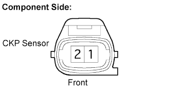
| 2.INSPECT CRANKSHAFT POSITION SENSOR (RESISTANCE) |
Disconnect the B22 Crankshaft Position (CKP) sensor connector.
Measure the resistance between terminals 1 and 2.
- Standard resistance:
Tester Connection
| Condition
| Specified Condition
|
1 - 2
| Cold
| 985 to 1,600 Ω
|
1 - 2
| Hot
| 1,265 to 1,890 Ω
|
- HINT:
- Terms cold and hot refer to the temperature of the sensor. Cold means approximately -10 to 50°C (14 to 122°F). Hot means approximately 50 to 100°C (122 to 212°F).
Reconnect the CKP sensor connector.
| | REPLACE CRANKSHAFT POSITION SENSOR |
|
|
| 3.CHECK HARNESS AND CONNECTOR (CRANKSHAFT POSITION SENSOR - ECM) |
Disconnect the B22 CKP sensor connector.
Disconnect the B32 ECM connector.
Measure the resistance of the wire harness side connectors.
- Standard resistance (Check for open):
Tester Connection
| Specified Condition
|
NE+ (B22-1) - NE+ (B32-122)
| Below 1 Ω
|
NE- (B22-2) - NE- (B32-121)
|
- Standard resistance (Check for short):
Tester Connection
| Specified Condition
|
NE+ (B22-1) or NE+ (B32-122) - Body ground
| 10 kΩ or higher
|
NE- (B22-2) or NE- (B32-121) - Body ground
|
Reconnect the ECM connector.
Reconnect the CKP sensor connector.
| | REPAIR OR REPLACE HARNESS OR CONNECTOR |
|
|
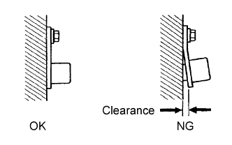
| 4.CHECK SENSOR INSTALLATION (CRANKSHAFT POSITION SENSOR) |
Check the CKP sensor installation.
- OK:
- Sensor is installed correctly.
| | SECURELY REINSTALL SENSOR |
|
|
| 5.CHECK CRANKSHAFT POSITION SENSOR PLATE (TEETH OF SENSOR PLATE) |
Check the teeth of the sensor plate.
- OK:
- Sensor plate does not have any cracks or deformation.
| | REPLACE CRANKSHAFT POSITION SENSOR PLATE |
|
|
| 6.REPLACE CRANKSHAFT POSITION SENSOR |
| 7.CHECK WHETHER DTC OUTPUT RECURS |
Connect an intelligent tester to the DLC3.
Turn the ignition switch on (IG) and turn the tester ON.
Clear DTCs (RAV4_ACA30 RM000000PDK0AHX.html).
Start the engine.
Select the following menu items: Powertrain / Engine and ECT / DTC.
Read DTCs.
- Result:
Display (DTC output)
| Proceed to
|
No output
| A
|
P0335 or P0339
| B
|
- HINT:
- If the engine does not start, replace the ECM.