Engine Unit -- Reassembly |
| 1. INSTALL PISTON WITH PIN SUB-ASSEMBLY |
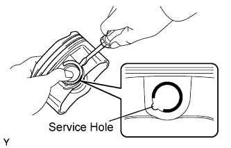
Using a screwdriver, install a new snap ring at one end of the piston pin hole.
- HINT:
- Be sure that the end gap of the snap ring is not aligned with the pin hole cutout portion of the piston.
 |
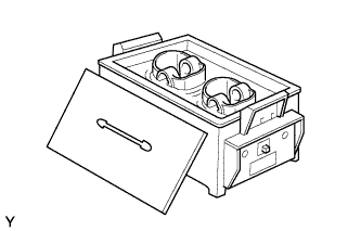
Gradually heat the piston to approximately 80°C (176°F).
 |
Coat the piston pin with engine oil.
Align the front marks of the piston and connecting rod, and push in the piston pin with your thumb.
- HINT:
- The piston and pin are a matched set.
 |
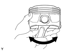
Check the fitting condition between the piston and piston pin by trying to move the piston back and forth on the piston pin.
 |
Using a screwdriver, install a new snap ring at the other end of the piston pin hole.
- HINT:
- Be sure that the end gap of the snap ring is not aligned with the pin hole cutout portion of the piston.
 |
| 2. INSTALL PISTON RING SET |
Install the oil ring expander and 2 side rails by hand.
Using a piston ring expander, install the 2 compression rings so that the painted marks are positioned as shown in the illustration.
 |
Position the piston rings so that the ring ends are as shown in the illustration.
- NOTICE:
- Do not align the ring ends.
 |
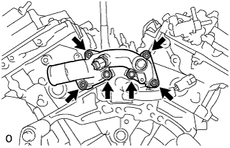
| 3. INSTALL NO. 1 OIL NOZZLE SUB-ASSEMBLY |
Using a 5 mm hexagon wrench, install the 3 oil nozzles with the bolts.
- Torque:
- 9.0 N*m{92 kgf*cm, 80 in.*lbf}
 |
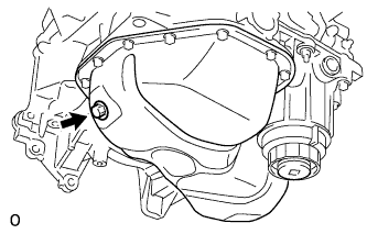
| 4. INSTALL CYLINDER BLOCK WATER DRAIN COCK SUB-ASSEMBLY |
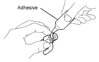
Apply adhesive around the drain cocks.
- Adhesive:
- Toyota Genuine Adhesive 1324, Three Bond 1324 or equivalent
 |
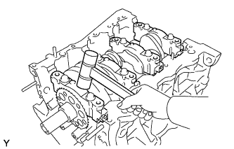
Install the cylinder block water drain cocks.
Temporarily install the drain cocks.
- Torque:
- 25 N*m{255 kgf*cm, 18 ft.*lbf}
Within one full rotation, tighten the drain cock to the angle shown in the illustration.
- Torque:
- 45 N*m{459 kgf*cm, 33 ft.*lbf}
- NOTICE:
- Do not loosen the drain cock to adjust it. If an adjustment is necessary, remove the drain cock and reinstall it.

Install the water drain cock plug to the water drain cocks.
- Torque:
- 13 N*m{130 kgf*cm, 9 ft.*lbf}
| 5. INSTALL CRANKSHAFT BEARING |
- NOTICE:
- Main bearings come in widths between 18.0 mm (0.709 in.) and 21.0 mm (0.827 in.). Install the 21.0 mm (0.827 in.) bearings for the No. 1 and No. 4 cylinder block journals with the main bearing cap. Install the 18.0 mm (0.709 in.) bearings in the No. 2 and No. 3 journals.
Clean the main journal and both surfaces of the bearing.
 |
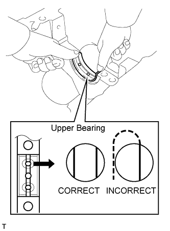
Install the upper bearing.
Install the upper bearing to the cylinder block as shown in the illustration.
- NOTICE:
- Do not apply engine oil to the bearing and its contact surface.
Install the lower bearing.
Install the lower bearing to the bearing cap.
Using a vernier caliper, measure the distance between the bearing cap's edge and the lower bearing's edge.
- Dimension (A - B):
- 0.7 mm (0.028 in.) or less.
- NOTICE:
- Do not apply engine oil to the bearing's contact area and underside.

| 6. INSTALL CRANKSHAFT |
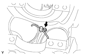
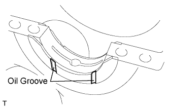
Install the 2 thrust washers under the No. 2 journal position of the cylinder block with the oil grooves facing outward.
 |
Apply engine oil to the upper bearing, and then place the crankshaft on the cylinder block.
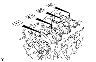
Confirm the front marks and numbers of the main bearing caps and install the bearing caps on the cylinder block.
- HINT:
- A number is marked on each main bearing cap to indicate the installation position.
 |
Apply a light coat of engine oil on the threads and under the heads of the bearing cap bolts.
Temporarily install the 8 main bearing cap bolts to the inside positions.
Insert the main bearing cap by hand until the clearance between the main bearing cap and the cylinder block is less than 6 mm (0.23 in.) by marking the 2 internal bearing cap bolts as a guide.
- Bolt length:
- 100.0 to 102.0 mm (3.937 to 4.016 in.)
 |
Using a plastic-faced hammer, lightly tap the bearing cap to ensure a proper fit.
 |
Apply a light coat of engine oil to the threads and under the heads of the 8 main bearing cap bolts.
Install the 8 main bearing cap bolts to the outside positions.
- Bolt length:
- 105.5 to 107.5 mm (4.154 to 4.232 in.)
 |
Install the crankshaft bearing cap bolts.
- HINT:
- The main bearing cap bolts are tightened in 2 progressive steps.
Step 1
Install and uniformly tighten the 16 main bearing cap bolts in the sequence shown in the illustration.
- Torque:
- 61 N*m{622 kgf*cm, 45 ft.*lbf}

Step 2
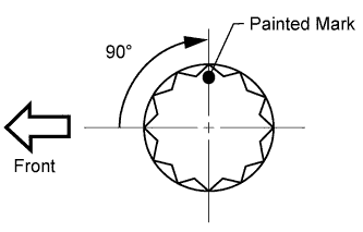
Mark the front of the bearing cap bolts with paint.
Tighten the bearing cap bolts another 90° in the order shown in step 1.
Check that the painted mark is now at a 90° angle from the front.
Check that the crankshaft turns smoothly.
Install and uniformly tighten the 8 main bearing cap bolts in several steps, in the sequence shown in the illustration.
- Torque:
- 52 N*m{530 kgf*cm, 38 ft.*lbf}
- Bolt length:
- 45 mm (1.77 in.) for bolt A
- 30 mm (1.18 in.) for except bolt A
 |
Check that the crankshaft turns smoothly.
| 7. INSTALL CONNECTING ROD BEARING |
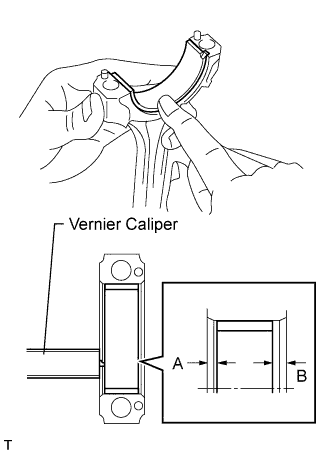
Install the connecting rod bearing to the connecting rod and bearing cap.
Using a vernier caliper, measure the distance between the connecting rod's and bearing cap's edges, and each connecting rod bearing's edge.
- Dimension (A - B):
- 0.7 mm (0.028 in.) or less
- NOTICE:
- Do not apply engine oil to the bearing's contact area and underside.
 |
| 8. INSTALL PISTON SUB-ASSEMBLY WITH CONNECTING ROD |
Apply engine oil to the cylinder walls, the pistons, and the surfaces of the connecting rod bearings.
Position the piston rings so that the ring ends are as shown in the illustration.
- NOTICE:
- Do not align the ring ends.
 |
Using a piston ring compressor, push the correctly numbered piston and connecting rod into the cylinder with the front mark of the piston facing forward.
- NOTICE:
- Match the numbered connecting rod cap with the connecting rod.
 |
Check that the front mark of the connecting rod cap is facing forward.
 |
Apply a light coat of engine oil to the threads and under the heads of the connecting rod cap bolts.
Install the connecting rod cap bolts.
- HINT:
- The connecting rod cap bolts are tightened in 2 progressive steps.
Step 1
Install and alternately tighten the bolts of the connecting rod cap in several steps.
- Torque:
- 25 N*m{255 kgf*cm, 18 ft.*lbf}
Step 2
Mark the front side of each connecting cap bolt with paint.
Retighten the cap bolts 90° as shown in the illustration.
Check that the painted mark is now at a 90° angle from the front.

Check that the crankshaft turns smoothly.
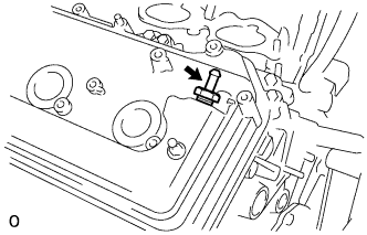
| 9. INSTALL CRANK POSITION SENSOR |
Install the crank position sensor with the bolt.
- Torque:
- 10 N*m{102 kgf*cm, 7 ft.*lbf}
 |
| 10. INSTALL NO. 2 STRAIGHT SCREW PLUG |
Using a 14 mm hexagon wrench, install 2 new gaskets and the 2 straight screw plugs.
- Torque:
- 80 N*m{816 kgf*cm, 59 ft.*lbf}
 |
| 11. INSTALL NO. 1 STRAIGHT SCREW PLUG |
Using a 10 mm hexagon wrench, install 4 new gaskets and the straight screw plugs.
- Torque:
- 44 N*m{449 kgf*cm, 32 ft.*lbf}
 |
| 12. INSTALL VALVE SPRING SEAT |
Install the valve spring seats to the cylinder head.
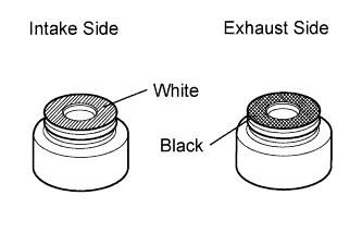
| 13. INSTALL VALVE STEM OIL SEAL |
Apply a light coat of engine oil to new oil seals.
- NOTICE:
- Pay attention when installing the intake and exhaust oil seals. For example, installing the intake oil seal into the exhaust side or installing the exhaust oil seal to the intake side can cause installation problems later.
- HINT:
- The intake valve oil seals are white and the exhaust valve oil seals are black.
 |
Using SST, push in the oil seals.
- SST
- 09201-41020
- NOTICE:
- Failure to use SST will cause the seal to be damaged or improperly seated.
 |
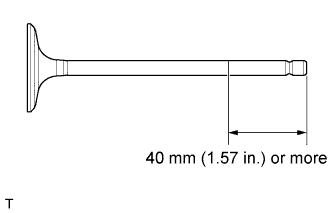
| 14. INSTALL INTAKE VALVE |
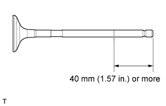
Apply plenty of engine oil to the tip area of the intake valve shown in the illustration.
 |
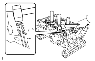
Install the valve, compression spring and spring retainer to the cylinder head.
- NOTICE:
- Install the same parts in the same combination to original locations.
Using SST and wooden blocks, compress the spring and install the retainer lock.
- SST
- 09202-70020(09202-00010)
 |
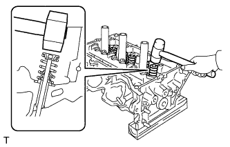
Using a plastic-faced hammer, lightly tap the valve stem tip to ensure a proper fit.
- NOTICE:
- Be careful not to damage the retainer.
 |
| 15. INSTALL EXHAUST VALVE |
Apply plenty of engine oil to the tip area of the exhaust valve shown in the illustration.
 |
Install the valve, compression spring and spring retainer to the cylinder head.
- NOTICE:
- Install the same parts in the same combination to their original locations.
Using SST and wooden blocks, compress the spring and install the retainer lock.
- SST
- 09202-70020(09202-00010)
 |
Using a plastic-faced hammer, lightly tap the valve stem tip to ensure a proper fit.
- NOTICE:
- Be careful not to damage the retainer.
 |
| 16. INSTALL VALVE STEM CAP |
Apply a light coat of engine oil to the valve stem caps.
Install the valve stem caps to the cylinder head.
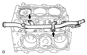
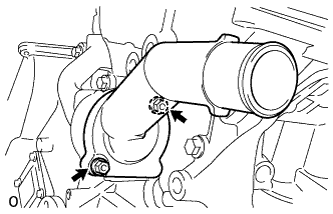
| 17. INSTALL WATER INLET PIPE |
Install the water inlet pipe with the 2 bolts.
- Torque:
- 10 N*m{102 kgf*cm, 7 ft.*lbf}
 |
Install the water by-pass hose.
| 18. INSTALL CYLINDER HEAD SUB-ASSEMBLY (for Bank 1) |
Check the piston protrusions for each cylinder.
Clean the cylinder block with solvent.
Set the piston of the cylinder to be measured to slightly before TDC.
Place the cylinder head gasket on the cylinder block surface with the front face of the Lot No. stamp facing upward.
- NOTICE:
- Be careful of the installation direction.
- Gently place the cylinder head in order not to damage the gasket with the bottom part of the head.
 |
Place the cylinder head on the cylinder block.
- NOTICE:
- Ensure that no oil is on the mounting surface of the cylinder head.
- HINT:
- The cylinder head bolts are tightened in 3 progressive steps.
Apply a light coat of engine oil to the threads and under the heads of the cylinder head bolts.
Step 1
Using a 10 mm bi-hexagon wrench, install and uniformly tighten the 8 cylinder head bolts with the plate washers in several steps, in the sequence shown in the illustration.
- Torque:
- 36 N*m{367 kgf*cm, 27 ft.*lbf}

Step 2
Mark the cylinder head bolt head with paint as shown in the illustration.
Tighten the cylinder heads bolts another 90° in the sequence shown in step 1.

Step 3
Tighten the cylinder head bolts by an additional 90° in the sequence shown in step 1.
Check that the painted mark is now facing rearward.
| 19. INSTALL CYLINDER HEAD SUB-ASSEMBLY (for Bank 2) |
Check the piston protrusions for each cylinder.
Clean the cylinder block with solvent.
Set the piston of the cylinder to be measured to slightly before TDC.
Place the cylinder head gasket on the cylinder block surface with the front face of the Lot No. stamp facing upward.
- NOTICE:
- Be careful of the installation direction.
- Gently place the cylinder head in order not to damage the gasket with the bottom part of the head.
 |
Place the cylinder head on the cylinder block.
- NOTICE:
- Ensure that no oil is on the mounting surface of the cylinder head.
- HINT:
- The cylinder head bolts are tightened in 3 progressive steps.
Apply a light coat of engine oil to the threads and under the heads of the cylinder head bolts.
Step 1
Using a 10 mm bi-hexagon wrench, install and uniformly tighten the 8 cylinder head bolts with the plate washers in several steps, in the sequence shown in the illustration.
- Torque:
- 36 N*m{367 kgf*cm, 27 ft.*lbf}

Step 2
Mark the cylinder head bolt heads with paint as shown in the illustration.
Tighten the cylinder head bolts another 90° in the sequence shown in step 1.
Step 3
Tighten the cylinder head bolts by an additional 90° in the sequence shown in step 1.
Check that the painted mark is now facing rearward.
Install the 2 bolts in the order shown in the illustration.
- Torque:
- 30 N*m{306 kgf*cm, 22 ft.*lbf}
 |
| 20. INSTALL VALVE LASH ADJUSTER ASSEMBLY |
Be sure to inspect the valve lash adjuster before installing it (RAV4_ACA30 RM000000XCV02IX_01_0016.html).
Install the lash adjusters.
- NOTICE:
- Install the lash adjuster to the same place it was removed from.
| 21. INSTALL NO. 1 VALVE ROCKER ARM SUB-ASSEMBLY |
Apply engine oil to the lash adjuster tips and valve stem cap ends.
Make sure that the valve rocker arms are installed as shown in the illustration.
 |
| 22. INSTALL NO. 1 CAMSHAFT |
Apply engine oil to the camshaft journals, camshaft housings and bearing caps.
Install the No. 1 camshaft to the camshaft housing.
| 23. INSTALL NO. 2 CAMSHAFT |
Apply engine oil to the camshaft journals, camshaft housings and bearing caps.
Install the No. 2 camshaft to the camshaft housing.
| 24. INSTALL CAMSHAFT BEARING CAP (for Bank 1) |
Confirm the marks and numbers on the camshaft bearing caps and place them each in their proper position and direction.
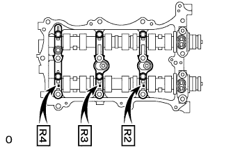 |
Temporarily install the 8 bolts in the order shown in the illustration.
- Torque:
- 10 N*m{102 kgf*cm, 7 ft.*lbf}
 |
| 25. INSTALL CAMSHAFT HOUSING SUB-ASSEMBLY (for Bank 1) |
Apply seal packing in a continuous line as shown in the illustration.
- Seal packing:
- Toyota Genuine Seal Packing Black, Three Bond 1207B or equivalent
- Standard seal diameter:
- 3.5 to 4.5 mm (0.138 to 0.177 in.)
- NOTICE:
- Remove any oil from the contact surface.
- Install the camshaft housing within 3 minutes and tighten the bolts within 15 minutes after applying seal packing.
- Do not start the engine for at least 2 hours after the installation.
 |
Install the camshaft housing, and install the 12 bolts in the order shown in the illustration.
- Torque:
- 28 N*m{286 kgf*cm, 21 ft.*lbf}
- NOTICE:
- Make sure that the knock pin of the camshaft is positioned as shown in the illustration before installing the camshaft housing.
 |
Tighten the 8 bolts in the order shown in the illustration.
- Torque:
- 16 N*m{163 kgf*cm, 12 ft.*lbf}
- NOTICE:
- Thoroughly wipe clean any seal packing.
 |
Install 3 new gaskets.
 |
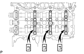
| 26. INSTALL NO. 3 CAMSHAFT |
Apply engine oil to the camshaft journals, camshaft housings and bearing caps.
Install the No. 3 camshaft to the camshaft housing.
| 27. INSTALL NO. 4 CAMSHAFT |
Apply engine oil to the camshaft journals, camshaft housings and bearing caps.
Install the No. 4 camshaft to the camshaft housing.
| 28. INSTALL CAMSHAFT BEARING CAP (for Bank 2) |
Confirm the marks and numbers on the camshaft bearing caps and place them each in their proper position and direction.
 |
Temporarily install the 8 bolts in the order shown in the illustration.
- Torque:
- 10 N*m{102 kgf*cm, 7 ft.*lbf}
 |
| 29. INSTALL CAMSHAFT HOUSING SUB-ASSEMBLY (for Bank 2) |
Apply seal packing in a continuous line as shown in the illustration.
- Seal packing:
- Toyota Genuine Seal Packing Black, Three Bond 1207B or equivalent
- Standard seal diameter:
- 3.5 to 4.5 mm (0.138 to 0.177 in.)
- NOTICE:
- Remove any oil from the contact surface.
- Install the camshaft housing within 3 minutes and tighten the bolts within 15 minutes after applying seal packing.
- Do not start the engine for at least 2 hours after the installation.
 |
Install the camshaft housing and tighten the 13 bolts in the order shown in the illustration.
- Torque:
- 28 N*m{286 kgf*cm, 21 ft.*lbf}
- NOTICE:
- Make sure that the knock pin of the camshaft is positioned as shown in the illustration before installing the camshaft housing.
 |
Tighten the 8 bolts in the order shown in the illustration.
- Torque:
- 16 N*m{163 kgf*cm, 12 ft.*lbf}
- NOTICE:
- Thoroughly wipe clean any seal packing.
 |
Install 3 new gaskets.
 |
| 30. INSTALL NO. 2 CHAIN TENSIONER ASSEMBLY |
Install the chain tensioner with the bolt.
- Torque:
- 21 N*m{214 kgf*cm, 15 ft.*lbf}
 |
While pushing in the tensioner, insert a pin of φ1.0 mm (0.039 in.) into the hole to fix it in place.
| 31. INSTALL CAMSHAFT TIMING GEARS AND NO. 2 CHAIN (for Bank 1) |
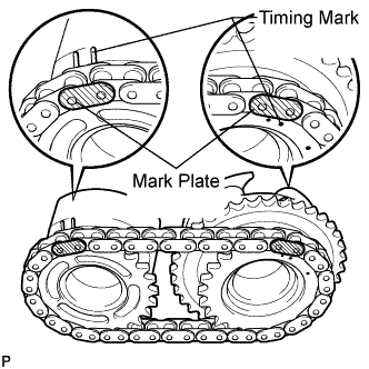
Align the mark plates (yellow) with the timing marks (1 dot mark) of the camshaft timing gears as shown in the illustration.
 |
Apply a small amount of engine oil to the bolt threads and bolt-seating surface.
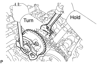
Align the knock pin of the camshaft with the pin hole of the camshaft timing gear. Install the camshaft timing gear and camshaft timing exhaust gear with the No. 2 chain installed.
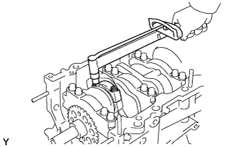
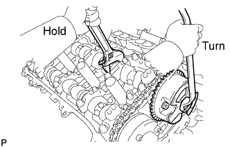
Hold the hexagonal portion of the camshaft with a wrench, and tighten the 2 bolts.
- Torque:
- 100 N*m{1020 kgf*cm, 74 ft.*lbf}
 |
Remove the pin from the No. 2 chain tensioner.
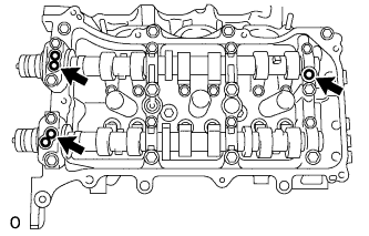
| 32. INSTALL NO. 3 CHAIN TENSIONER ASSEMBLY |
Install the chain tensioner with the bolt.
- Torque:
- 21 N*m{214 kgf*cm, 15 ft.*lbf}
 |
While pushing in the tensioner, insert a pin of φ1.0 mm (0.039 in.) into the hole to fix it in place.
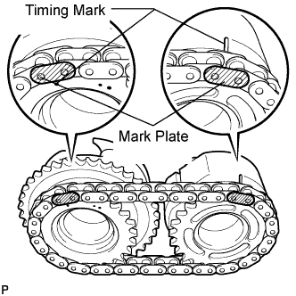
| 33. INSTALL CAMSHAFT TIMING GEARS AND NO. 2 CHAIN (for Bank 2) |
Align the mark plates (yellow) with the timing marks (2 dot mark) of the camshaft timing gears as shown in the illustration.
 |
Apply a small amount of engine oil to the bolt threads and bolt-seating surface.
Align the knock pin of the camshaft with the pin hole of the camshaft timing gear. Install the camshaft timing gear and camshaft timing exhaust gear with the No. 2 chain installed.
Hold the hexagonal portion of the camshaft with a wrench, and tighten the 2 bolts.
- Torque:
- 100 N*m{1020 kgf*cm, 74 ft.*lbf}
 |
Remove the pin from the No. 2 chain tensioner.
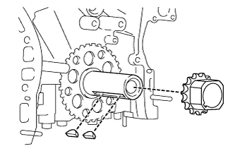
| 34. INSTALL CRANKSHAFT TIMING GEAR OR SPROCKET |
Install the timing gear set keys and timing gear as shown in the illustration.
 |
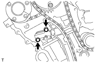
| 35. INSTALL NO. 1 CHAIN VIBRATION DAMPER |
Install the chain vibration damper with the 2 bolts.
- Torque:
- 23 N*m{235 kgf*cm, 17 ft.*lbf}
 |
| 36. INSTALL NO. 2 CHAIN VIBRATION DAMPER |
Install the 2 chain vibration dampers.
| 37. INSTALL IDLE SPROCKET ASSEMBLY |
Apply a light coat of engine oil to the rotating surface of the No. 1 idle gear shaft.
Temporarily install the No. 1 idle gear shaft and idle sprocket with the No. 2 idle gear shaft while aligning the knock pin of the No. 1 idle gear shaft with the knock pin groove of the cylinder block.
- NOTICE:
- Make sure that the idle gear is facing the correct direction.
 |
Using a 10 mm hexagon wrench, tighten the No. 2 idle gear shaft.
- Torque:
- 60 N*m{612 kgf*cm, 44 ft.*lbf}
| 38. INSTALL NO. 1 CHAIN SUB-ASSEMBLY |
Align the mark plates and timing marks as shown in the illustration and install the chain.
- NOTICE:
- Do not pass the chain over the crankshaft. Rest the chain on top of the crankshaft.
- HINT:
- The chain mark plate is orange.
 |
Turn the camshaft timing gear on the bank 1 counterclockwise to tighten the chain between the banks.
- NOTICE:
- If reusing the idle sprocket, align one of the idle sprocket's chain plate marks with one of the chain's chain plates when installing the idle sprocket.
 |
Align the mark plate and timing mark as shown in the illustration and install the chain onto the crankshaft timing gear.
- HINT:
- The chain mark plate is yellow.
 |
Temporarily tighten the pulley set bolt.
Turn the crankshaft clockwise to set it to the bank 1 block bore center line (TDC / compression).
 |
| 39. INSTALL CHAIN TENSIONER SLIPPER |
Install the chain tensioner slipper.
| 40. INSTALL NO. 1 CHAIN TENSIONER ASSEMBLY |
Move the stopper plate upward to release the lock, and push the plunger deep into the tensioner.
 |
Move the stopper plate downward to set the lock, and insert a hexagon wrench into the hole of the stopper plate.
Install the chain tensioner with the 2 bolts.
- Torque:
- 10 N*m{102 kgf*cm, 7 ft.*lbf}
 |
Remove the lock pin of the chain tensioner. Check that each timing mark is aligned with the crankshaft at the TDC / compression.
 |
Remove the pulley set bolt.
| 41. INSTALL TIMING CHAIN COVER SUB-ASSEMBLY |
Install a new gasket.
 |
Align the oil pump's drive rotor spline and the crankshaft as shown in the illustration.
 |
Apply seal packing in a continuous bead to the engine unit as shown in the illustration.

- Seal packing:
- Toyota Genuine Seal Packing Block, Three Bond 1207B or equivalent
- Standard seal diameter:
- 3.0 mm (0.118 in.) or more
- Standard length:
- 10 mm (0.394 in.)
- NOTICE:
- Be sure to clean and degrease the contact surfaces, especially the hatched areas in the illustration.
- When the contact surfaces are wet, wipe them off with an oil-free cloth before applying seal packing.
- Install the timing chain cover within 3 minutes and tighten the bolts within 15 minutes after applying seal packing.
- Do not start the engine for at least 2 hours after installing the timing chain cover.
Apply seal packing in a continuous line to the timing chain cover as shown in the illustration.

- Seal packing:
- For oil related part:
Toyota Genuine Seal Packing Black, Three Bond 1207B or equivalent - For water related part:
Toyota Genuine Seal Packing 1282B, Three Bond 1282B or equivalent
- Standard seal diameter:
Position Specified Condition A - A 6.0 mm (0.236 in.) B - B 6.5 mm (0.256 in.) Continuous line area 4.5 mm (0.177 in.) or more Dashed line area 3.5 mm (0.138 in.) or more Alternate long and short dashed line area 3.5 mm (0.138 in.) or more
- NOTICE:
- When the contact surfaces are wet, wipe them off with an oil-free cloth before applying seal packing.
- Install the timing chain cover within 3 minutes and tighten the bolts within 15 minutes after applying seal packing.
- Do not start the engine for at least 2 hours after installing the timing chain cover.
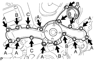
Temporarily install the timing chain cover with the 23 bolts and 2 nuts.

- NOTICE:
- Make sure that there is no oil on the bolts. If there is oil on the bolts, clean them before installing them.
- HINT:
- Bolt length:
- 40 mm (1.57 in.) for bolt A
- 55 mm (2.17 in.) for bolt B
- 25 mm (0.98 in.) for bolt C
Tighten the bolts in this order: Area 1, Area 2, Area 3, Area 4.
- Torque:
- 21 N*m{214 kgf*cm, 15 ft.*lbf}for bolts in Area 1 and 2
- 21 N*m{214 kgf*cm, 15 ft.*lbf}for bolts and nuts in Area 3
- 43 N*m{438 kgf*cm, 32 ft.*lbf}for bolt A in Area 4
- 21 N*m{214 kgf*cm, 15 ft.*lbf}for bolts except A in Area 4
| 42. INSTALL WATER PUMP ASSEMBLY |
Install a new water pump gasket and the water pump with the 16 bolts.
- Torque:
- for bolt A:
- 21 N*m{214 kgf*cm, 15 ft.*lbf}
- for bolt B and C:
- 11 N*m{112 kgf*cm, 8 ft.*lbf}
- NOTICE:
- Be sure to replace 2 bolts C with new ones or reuse them after applying adhesive.
Adhesive:
Toyota Genuine Adhesive 1344, Three Bond 1344 or equivalent - Make sure that there is no oil on the threads of bolts A.
 |
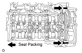
| 43. INSTALL ENGINE REAR OIL SEAL RETAINER |
Apply seal packing in a continuous line as shown in the illustration.
- Seal packing:
- Toyota Genuine Seal Packing Black, Three Bond 1207B or equivalent
- Standard seal diameter:
- 2.0 to 3.0 mm (0.079 to 0.118 in.)
- NOTICE:
- Remove any oil from the contact surface.
- Install the crankcase within 3 minutes after applying seal packing.
- Do not start the engine for at least 2 hours after the installation.
 |
Install the oil seal retainer with the 6 bolts.
- Torque:
- 10 N*m{102 kgf*cm, 7 ft.*lbf}
- NOTICE:
- Apply adhesive 1324 to the 2 bolts labeled A.
- Adhesive:
- Toyota Genuine Adhesive 1324, Three Bond 1324 or equivalent
 |
| 44. INSTALL CRANKSHAFT PULLEY |
Align the pulley set key with the key groove of the pulley, and slide on the pulley.
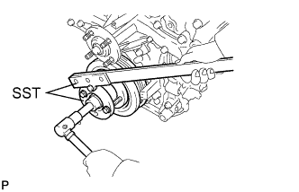 |
Using SST, install the pulley bolt.
- SST
- 09213-70011(09213-70020)
09330-00021
- Torque:
- 250 N*m{2549 kgf*cm, 184 ft.*lbf}
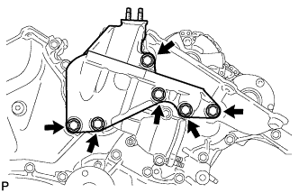
| 45. INSTALL NO. 1 OIL PAN BAFFLE PLATE |
Install the oil pan baffle plate with the 7 bolts.
- Torque:
- 10 N*m{102 kgf*cm, 7 ft.*lbf}
 |
| 46. INSTALL OIL PAN SUB-ASSEMBLY |
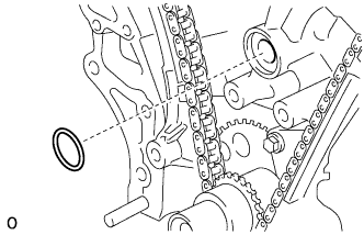
Install 2 new O-rings to the timing chain cover.
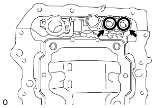 |
Apply seal packing in a continuous line as shown in the illustration.
- Seal packing:
- Toyota Genuine Seal Packing Black, Three Bond 1207B or equivalent
- Standard seal diameter:
- 3.0 to 4.0 mm (0.118 to 0.156 in.)
- NOTICE:
- Remove any oil from the contact surface.
- Install the oil pan within 3 minutes and tighten the bolts within 15 minutes after applying seal packing.
- Do not start the engine for at least 2 hours after installing the oil pan.
 |
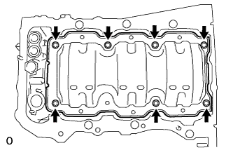
Install the oil pan with the 16 bolts and 2 nuts.
- Torque:
- 10 N*m{102 kgf*cm, 7 ft.*lbf}for bolt A
- 21 N*m{214 kgf*cm, 15 ft.*lbf}for bolts except A and nuts
 |
| 47. INSTALL OIL STRAINER SUB-ASSEMBLY |
Install a new gasket and the oil strainer with the bolt and 2 nuts.
- Torque:
- 10 N*m{102 kgf*cm, 7 ft.*lbf}
 |
| 48. INSTALL NO. 2 OIL PAN SUB-ASSEMBLY |
Apply seal packing in a continuous line as shown in the illustration.
- Seal packing:
- Toyota Genuine Seal Packing Black, Three Bond 1207B or equivalent
- Standard seal diameter:
- 3.0 to 4.0 mm (0.118 to 0.156 in.)
- NOTICE:
- Remove any oil from the contact surface.
- Install the oil pan within 3 minutes and tighten the bolts within 10 minutes after applying seal packing.
- Do not start the engine for at least 2 hours after installing the oil pan.
 |
Install the oil pan with the 16 bolts and 2 nuts.
- Torque:
- 10 N*m{102 kgf*cm, 7 ft.*lbf}
 |
Install a new gasket and the drain plug.
- Torque:
- 40 N*m{408 kgf*cm, 30 ft.*lbf}
| 49. INSTALL OIL FILTER ELEMENT |
Clean the oil filter cap threads and O-ring groove.
Apply a small amount of engine oil to a new O-ring and install it to the oil filter cap.
 |
Set a new oil filter element in the oil filter cap.
| 50. INSTALL OIL FILTER CAP ASSEMBLY |
Remove any dirt or foreign matter from the installation surface and inside of the engine.
Apply a small amount of engine oil to the O-ring again and install the oil filter cap.
- NOTICE:
- Make sure that the O-ring does not get caught between the parts.
Using SST, tighten the oil filter cap.
- SST
- 09228-06501
- Torque:
- 25 N*m{255 kgf*cm, 18 ft.*lbf}
- NOTICE:
- Make sure that the oil filter is installed securely as shown in the illustration.
- Make sure that the O-ring does not get caught between the parts.
 |
Apply a small amount of engine oil to a new drain plug O-ring, and install it to the oil filter cap.
- NOTICE:
- Before installing the O-ring, remove any dirt or foreign matter from the installation surface of the oil filter cap.
 |
Install the oil filter drain plug to the filter cap.
- Torque:
- 12.5 N*m{127 kgf*cm, 9 ft.*lbf}
- NOTICE:
- Make sure that the O-ring does not get caught between the parts.
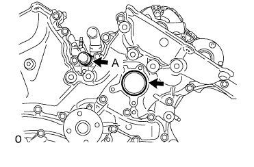
| 51. INSTALL WATER INLET HOUSING |
Install 2 new O-rings.
- HINT:
- Apply a small amount of water or soapy water to O-ring (A) in the illustration before installing it.
 |
Install the water inlet with the 2 bolts and nut.
- Torque:
- 10 N*m{102 kgf*cm, 7 ft.*lbf}
- NOTICE:
- Be careful that the O-ring does not get caught between the parts.
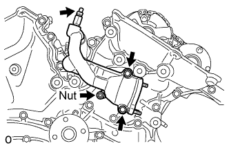 |
Connect the No. 1 water by-pass hose.
Apply adhesive around the drain cock.
- Adhesive:
- Toyota Genuine Adhesive 1324, Three Bond 1324 or equivalent
Install the drain cock to the water inlet housing.
- Torque:
- 30 N*m{306 kgf*cm, 22 ft.*lbf}
Install the drain cock plug to the water drain cock.
- Torque:
- 13 N*m{130 kgf*cm, 9 ft.*lbf}
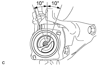
Install a new gasket to the thermostat.
Align the thermostat jiggle valve with the upper stud bolt, and insert the thermostat in the water inlet housing.
- HINT:
- The jiggle valve may be set within 10° of either side of the prescribed positions.
 |
Install the water inlet with the 2 nuts.
- Torque:
- 10 N*m{102 kgf*cm, 7 ft.*lbf}
 |
| 52. INSTALL FRONT NO. 1 ENGINE MOUNTING BRACKET |
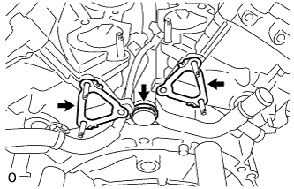
Install the engine mounting bracket with the 6 bolts.
- Torque:
- 54 N*m{551 kgf*cm, 40 ft.*lbf}
- NOTICE:
- Install the water inlet and mounting bracket within 15 minutes after installing the chain cover.
- Do not start the engine for at least 2 hours after the installation.
 |
| 53. INSTALL CYLINDER HEAD COVER SUB-ASSEMBLY (for Bank 1) |
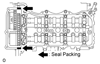
Apply seal packing as shown in the illustration.
- Seal packing:
- Toyota Genuine Seal Packing Black, Three Bond 1207B or equivalent
- NOTICE:
- Remove any oil from the contact surface.
- Install the crankcase within 3 minutes after applying seal packing.
- Do not start the engine for at least 2 hours after the installation.
 |
Install a new gasket to the head cover.
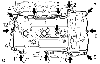
Install the head cover with the 12 bolts in the order shown in the illustration.
- Torque:
- for Bolt A:
- 21 N*m{214 kgf*cm, 15 ft.*lbf}
- for except Bolt A:
- 10 N*m{102 kgf*cm, 7 ft.*lbf}
- HINT:
- Make sure the tightening torque of bolts 1 and 11 is correct.
 |
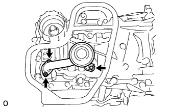
| 54. INSTALL OIL PIPE |
Make sure that there is no foreign matter on the mesh of the oil control valve filter.
 |
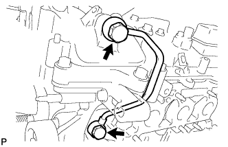
Install the oil control valve filter to the oil pipe union. Install 2 new gaskets and temporarily install the oil pipe (on the head cover side) with the oil pipe union.
- NOTICE:
- Remove any oil from the contact surface.
Install a new gasket and temporarily install the oil pipe (on the cylinder head side) with the oil pipe union.
- NOTICE:
- Remove any oil from the contact surface.
Install bolt A to the cylinder head.
- Torque:
- 10 N*m{102 kgf*cm, 7 ft.*lbf}
Tighten the 2 oil pipe union bolts.
- Torque:
- 65 N*m{663 kgf*cm, 48 ft.*lbf}
| 55. INSTALL CYLINDER HEAD COVER SUB-ASSEMBLY (for Bank 2) |
Apply seal packing as shown in the illustration.
- Seal packing:
- Toyota Genuine Seal Packing Black, Three Bond 1207B or equivalent
- NOTICE:
- Remove any oil from the contact surface.
- Install the crankcase within 3 minutes after applying seal packing.
- Do not start the engine for at least 2 hours after the installation.
 |
Install a new gasket to the head cover.
Install the head cover with the 12 bolts in the order in the illustration.
- Torque:
- 21 N*m{214 kgf*cm, 15 ft.*lbf}for bolt A
- 10 N*m{102 kgf*cm, 7 ft.*lbf}for except bolt A
- HINT:
- Make sure the tightening torque of bolts 1 and 10 is correct.
 |
| 56. INSTALL NO. 1 OIL PIPE |
Make sure that there is no foreign matter on the mesh of the oil control valve filter.
 |
Install the oil control valve filter to the oil pipe union. Install 2 new gaskets and temporarily install the oil pipe (on the head cover side) with the oil pipe union.
Install a new gasket and temporarily install the oil pipe (on the cylinder head side) with the oil pipe union.
- NOTICE:
- Remove any oil from the contract surface.
Tighten the 2 oil pipe union bolts.
- Torque:
- 65 N*m{663 kgf*cm, 48 ft.*lbf}
| 57. INSTALL WATER OUTLET |
Install 2 new gaskets and a new O-ring.
 |
Apply soapy water to the O-ring.
Install the water outlet with the 2 bolts and 4 nuts.
- Torque:
- 10 N*m{102 kgf*cm, 7 ft.*lbf}
 |
| 58. INSTALL CAMSHAFT TIMING OIL CONTROL VALVE ASSEMBLY |
Install the 4 camshaft timing oil control valves with the 4 bolts.
- Torque:
- 10 N*m{102 kgf*cm, 7 ft.*lbf}
 |
| 59. INSTALL CAMSHAFT POSITION SENSOR |
Install the 4 camshaft position sensors with the 4 bolts.
- Torque:
- 10 N*m{102 kgf*cm, 7 ft.*lbf}
 |
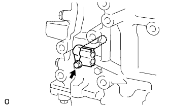
| 60. INSTALL VENTILATION VALVE SUB-ASSEMBLY |
Apply adhesive to 2 or 3 threads of the ventilation valve.
- Adhesive:
- Toyota genuine adhesive 1324, three bond 1324 or equivalent
 |
Install the ventilation valve sub-assembly.
- Torque:
- 27 N*m{275 kgf*cm, 20 ft.*lbf}
 |
| 61. INSTALL OIL PAN DRAIN PLUG |
Install the drain plug and gasket.
- Torque:
- 40 N*m{408 kgf*cm, 30 ft.*lbf}
 |
| 62. INSTALL SPARK PLUG |
Install the 6 spark plugs.
- Torque:
- 18 N*m{184 kgf*cm, 13 ft.*lbf}
| 63. INSTALL OIL FILLER CAP SUB-ASSEMBLY |
Install the oil filler cap sub-assembly.