Brake. Toyota Rav4. Aca30, 33, 38 Gsa33 Zsa30, 35
Brake Control. Toyota Rav4. Aca30, 33, 38 Gsa33 Zsa30, 35
Vehicle Stability Control System -- Terminals Of Ecu |
| SKID CONTROL ECU |

| Terminal No. (Symbol) | Terminal Description |
| 1 (GND1) | Skid control ECU ground |
| 2 (STP) | Stop light switch input |
| 4 (RL-) | Rear LH wheel speed signal input |
| 5 (RL+) | Rear LH wheel speed sensor power supply |
| 6 (FR-) | Front RH wheel speed signal input |
| 7 (FR+) | Front RH wheel speed sensor power supply |
| 11 (SP1) | Speed signal output for speedometer |
| 12 (+BS) | Solenoid valve power supply |
| 13 (GND2) | Motor ground |
| 14 (CANL) | CAN communication line L |
| 16 (RR-) | Rear RH wheel speed signal input |
| 17 (RR+) | Rear RH wheel speed signal power supply |
| 18 (FL-) | Front LH wheel speed signal input |
| 19 (FL+) | Front LH wheel speed sensor power supply |
| 22 (STP2) | Stop light control relay input |
| 24 (BM) | Motor power supply |
| 25 (CANH) | CAN communication line H |
| 27 (FSW+)*1 | Brake pedal load sensing switch input |
| 29 (HDCS)*2 | Downhill assist control switch input |
| 30 (CSW) | VSC OFF switch input |
| 31 (STPO) | Stop light control relay output |
| 33 (TS) | Sensor diagnosis check input |
| 34 (IG1) | ECU power supply |
- HINT:
- *1: w/ Booster Failure Compensation
- *2: w/ Downhill Assist Control
| CHECK SKID CONTROL ECU |

Disconnect the A67 ECU connector.
Measure the voltage and resistance of the wire harness side connector.
- HINT:
- The voltage cannot be measured with the connector connected to the skid control ECU as the connector is water resistant.
Skid Control ECU: Terminal No. (Symbol) Wiring Color Terminal Description Condition Specified Condition A67-1 (GND1) - Body ground W-B - Body ground Skid control ECU ground Always Below 1 Ω A67-2 (STP) - Body ground L - Body ground Stop light switch input Stop light switch off
Brake pedal releasedBelow 1.5 V Stop light switch on
Brake pedal depressed8 to 14 V A67-12 (+BS) - Body ground W - Body ground Solenoid valve power supply Always 11 to 14 V A67-13 (GND2) - Body ground W-B - Body ground Motor ground Always Below 1 Ω A67-22 (STP2) - Body ground L - Body ground Stop light control relay input Stop light switch off
Brake pedal releasedBelow 1.5 V Stop light switch on
Brake pedal depressed8 to 16 V A67-24 (BM) - Body ground B - Body ground Motor power supply Always 11 to 14 V A67-27 (FSW+)*1 - Body ground P - Body ground Brake pedal load sensing switch input Brake pedal load sensing switch on
Brake pedal not depressed beyond the specified point192 to 234 Ω Brake pedal load sensing switch off
Brake pedal depressed beyond the specified point0.9 to 1.1 kΩ A67-29 (HDCS)*2 - Body ground Y - Body ground Downhill assist control switch input Downhill assist control switch on Below 1 Ω Downhill assist control switch off 10 kΩ or higher A67-30 (CSW) - Body ground L - Body ground VSC OFF switch input VSC OFF switch on Below 1 Ω VSC OFF switch off 10 kΩ or higher A67-31 (STPO) - Body ground W - Body ground Stop light control relay output Ignition switch ON 11 to 14 V A67-34 (IG1) - Body ground L - Body ground ECU power supply Ignition switch ON 11 to 14 V - HINT:
- *1: w/ Booster Failure Compensation
- *2: w/ Downhill Assist Control
| CHECK INSTRUMENT PANEL JUNCTION BLOCK (MAIN BODY ECU) |
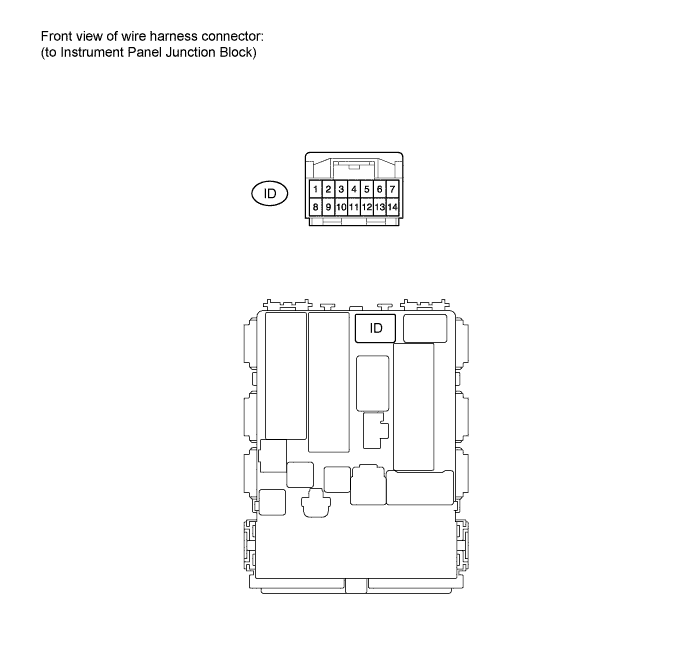
Disconnect the ID junction block connector.
Measure the resistance of the wire harness side connector.
If the result is not as specified, there may be a malfunction on the wire harness side.Terminal No. (Symbol) Wiring Color Terminal Description Condition Specified Condition ID-4 (PKB) - Body ground B - Body ground Parking brake switch input Parking brake switch on Below 1 Ω Parking brake switch off 10 kΩ or higher Reconnect the ID junction block connector.
Measure the voltage of the wire harness side connector.
If the result is not as specified, the junction block (main body ECU) may be a malfunction.Terminal No. (Symbol) Wiring Color Terminal Description Condition Specified Condition ID-4 (PKB) - Body ground B - Body ground Parking brake switch input Ignition switch ON
Parking brake switch onBelow 1 V Ignition switch ON
Parking brake switch off11 to 14 V