Dtc B15C2 Speed Signal Malfunction
DESCRIPTION
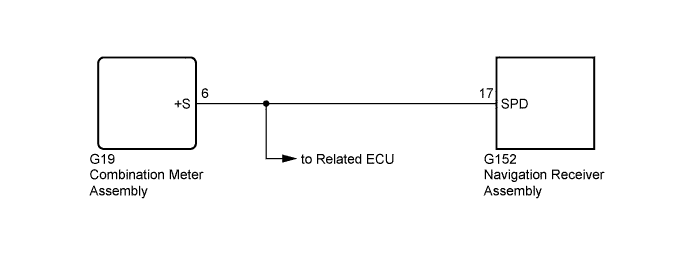
WIRING DIAGRAM
INSPECTION PROCEDURE
CHECK VEHICLE SENSOR (OPERATION CHECK)
DTC B15C2 Speed Signal Malfunction |
DESCRIPTION
The navigation receiver assembly receives a vehicle speed signal from the combination meter assembly and information about the navigation antenna, and then adjusts the vehicle position.The navigation receiver assembly stores this DTC when the difference between the speed information that the navigation antenna receives and the SPD pulse received from the combination meter assembly becomes large.- HINT:
- A voltage of 12 V or 5 V is output from each ECU and then input to the combination meter assembly. The signal is changed to a pulse signal at the transistor in the combination meter assembly. Each ECU controls the respective systems based on the pulse signal.
- If a short occurs in any of the ECUs or in the wire harness connected to an ECU, all systems in the diagram below will not operate normally.
DTC Code
| DTC Detection Condition
| Trouble Area
|
B15C2
| A difference between the GPS speed and SPD pulse is detected.
| - Harness or connector
- Combination meter assembly
- Navigation receiver assembly
|
WIRING DIAGRAM
INSPECTION PROCEDURE
| 1.CHECK VEHICLE SENSOR (OPERATION CHECK) |
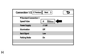
Display the "Connection Status" screen (HILUX_TGN26 RM000003A3N01WX.html).
While driving the vehicle, check that the value and gauge change in response to changes in vehicle speed.
- OK:
- The value and gauge change in response to changes in vehicle speed.