Can Communication System (W/ Vsc) -- Diagnosis System |
| BUS CHECK (COMMUNICATION MALFUNCTION ECU) |
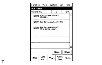
Select "Bus Check" from the "System Select" screen on the intelligent tester.
Select "Communication Malfunction DTC" from the "Bus Check" screen, and then select "Enter".
Select the system of the DTC to be checked and select "Details".
CAN communication system DTCs are output.
 |
 |
 |
 |
| BUS CHECK (COMMUNICATION BUS CHECK) |
- HINT:
- The ECUs and sensors that are properly connected to the CAN communication system can be displayed using the intelligent tester.
Select "Communication Bus Check" from the "Bus Check" screen.
The screen displays the ECUs and sensors that are properly connected to the CAN communication system.
- HINT:
- If any properly connected ECUs or sensors are not displayed, there is a communication stop in the system (HILUX_TGN26 RM000004PEO007X.html).
- The default item displayed in the combo box is "ALL". When checking the ECUs (sensors) connected to each bus, pull down the combo box and select the bus to be checked from the drop-down list. The drop-down list displays "ALL", "V Bus" and the names of the remaining buses.
Combo Box Display Content ALL All ECUs (sensors) connected to the CAN bus V Bus ECUs (sensors) connected to the V Bus Bus Name ECUs (sensors) connected to the selected bus - The connection status (shown below) is indicated by the background color displayed behind the system name.
ECU (Sensor) on V Bus Background Color Connection Status White Detected normally Yellow Could not be detected in the past, but is currently detected Red Detected in the past, but cannot be detected now Not displayed Has never been detected ECU (Sensor) with No Data Monitor History Background Color Connection Status White Detected normally Yellow Could not be detected in the past, but is currently detected Red Detected in the past, but cannot be detected now Not displayed Has never been detected ECU (Sensor) with Data Monitor History Background Color Connection Status White Detected normally Yellow Could not be detected in the past, but is currently detected Red Detected in the past, but cannot be detected now Red Has never been detected but has connection history Not displayed Has never been detected
"There is no system connected to the communication bus." is displayed if there are no ECUs or sensors connected to the CAN bus.
|
 |
| CHECK INSTALLED SYSTEMS (ECUS AND SENSORS) THAT USE CAN COMMUNICATION |
Systems (ECUs and sensors) that use CAN communication vary depending on the optional settings of the vehicle. Check which systems (ECUs and sensors) are installed on the vehicle.
ECU/Sensor Name Tester Display Installed on ECM ECM (Engine) All vehicles Transmission control ECU assembly (TCM) TCM All vehicles Brake actuator assembly (skid control ECU) Skid Control (ABS/VSC/TRAC) All vehicles Yaw rate sensor assembly Yaw Rate Sensor All vehicles Spiral cable sub-assembly (steering angle sensor) Spiral cable (Steering Angle Sensor) All vehicles
| DTC TABLE BY ECU |
- HINT:
- In the CAN communication system, CAN communication system DTCs stored by an ECU can be output by using the intelligent tester.
- If CAN communication system DTCs are output, the trouble cannot be determined solely from the DTCs. Perform troubleshooting according to "How to Proceed with Troubleshooting" (HILUX_TGN26 RM000004PEM007X.html).
ECM
- HINT:
- DTC communication uses the CAN communication system.
DTC Code Detection Item U0101* Lost Communication with TCM - *: Refer to the ECD system.
- w/ EGR Cooler (HILUX_TGN26 RM000001O2V09IX.html)
- w/o EGR Cooler (HILUX_TGN26 RM000001O2V09JX.html)
- for i-ART (HILUX_TGN26 RM000001O2V09GX.html)
TRANSMISSION CONTROL ECU ASSEMBLY (TCM)
- HINT:
- DTC communication uses the CAN communication system.
DTC Code Detection Item U0100* Lost Communication with ECM/PCM "A" - *: Refer to the automatic transmission system (HILUX_TGN26 RM000001RRQ05IX.html).
BRAKE ACTUATOR ASSEMBLY (SKID CONTROL ECU)
- HINT:
- DTC communication uses the CAN communication system.
DTC Code Detection Item U0073 Control Module Communication Bus Off U0100 Lost Communication with ECM/PCM "A" U0123 Lost Communication with Yaw Rate Sensor Module U0124 Lost Communication with Lateral Acceleration Sensor Module U0126 Lost Communication with Steering Angle Sensor Module YAW RATE SENSOR ASSEMBLY
- HINT:
- The yaw rate sensor assembly is connected to the CAN communication system but CAN communication DTCs are not stored.
SPIRAL CABLE SUB-ASSEMBLY (STEERING ANGLE SENSOR)
- HINT:
- The spiral cable sub-assembly (steering angle sensor) is connected to the CAN communication system but CAN communication DTCs are not stored.
| DTC COMBINATION TABLE |
- HINT:
- ○: Stored.
- -: Not stored.
| Output from | Output DTC | Detection Item | Detected Communication Stop Mode | |||
| V Bus | ||||||
| Skid Control ECU Communication Stop Mode | Yaw Rate Sensor Communication Stop Mode | Steering Angle Sensor Communication Stop Mode | ECM Communication Stop Mode | |||
| Brake actuator assembly (skid control ECU) | U0073 | Control Module Communication Bus Off | ○ | - | - | - |
| U0100 | Lost Communication with ECM/PCM "A" | ○ | - | - | ○ | |
| U0123 | Lost Communication with Yaw Rate Sensor Module | ○ | ○ | - | - | |
| U0124 | Lost Communication with Lateral Acceleration Sensor Module | ○ | ○ | - | - | |
| U0126 | Lost Communication with Steering Angle Sensor Module | ○ | - | ○ | - | |