Blocking System Engine Does Not Start
DESCRIPTION
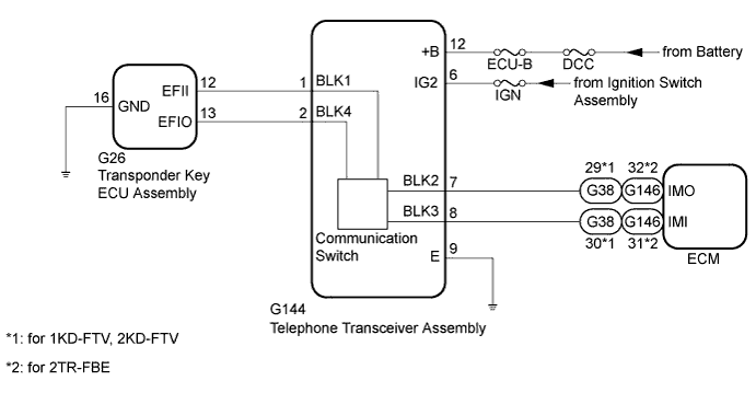
WIRING DIAGRAM
INSPECTION PROCEDURE
CHECK BLOCKING SYSTEM (SETTING)
CHECK TRANSPONDER KEY ECU ASSEMBLY (OUTPUT)
REPLACE TRANSPONDER KEY ECU ASSEMBLY
REGISTER ECU COMMUNICATION ID
CHECK WHETHER ENGINE STARTS
REGISTER ECU COMMUNICATION ID
CHECK WHETHER ENGINE STARTS
BLOCKING SYSTEM - Engine does not Start |
DESCRIPTION
If the engine does not start and no DTCs are output, the following conditions may apply.- There is an open or short circuit between the telephone transceiver assembly and the ECM or transponder key ECU assembly.
- The blocking system is set.
WIRING DIAGRAM
INSPECTION PROCEDURE
- NOTICE:
- Before troubleshooting this symptom, make sure no engine immobiliser system DTCs or blocking system DTCs are present. If present, troubleshoot the engine immobiliser system DTCs or blocking system DTCs first.
- When replacing the telephone transceiver assembly, refer to the Service Bulletin.
- When the telephone transceiver assembly is replaced, it is necessary to set the contract mode.
- Inspect the fuses for circuits related to this system before performing the following inspection procedure.
| 1.CHECK BLOCKING SYSTEM (SETTING) |
Check the blocking system setting.
- HINT:
- Check with the customer's contracted service provider to determine whether the blocking system is set.
ResultResult
| Proceed to
|
Blocking system is set.
| A
|
Blocking system is unset.
| B
|
| 2.CHECK TRANSPONDER KEY ECU ASSEMBLY (OUTPUT) |
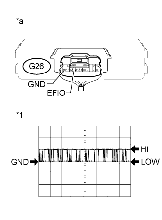
Using an oscilloscope, check the waveform.
Measurement Condition Item
| Content
|
Tester Connection
| G26-13 (EFIO) - G26-16 (GND)
|
Tool Setting
| 10 V/DIV., 100 ms./DIV.
|
Condition
| Ignition switch ON
|
- HINT:
- The waveform shown in the illustration is an example for reference only. Noise, chattering, etc. are not shown.
- Check the waveform when the security indicator light is off (the engine immobiliser system is unset). If the security indicator light does not turn off (the engine immobiliser system cannot be unset), refer to the engine immobiliser system.
- OK:
- Waveform is output normally (refer to illustration).
ResultResult
| Proceed to
|
NG (stuck LOW)
| A
|
NG (stuck HI)
| B
|
OK
| C
|
Text in Illustration*1
| Waveform
|
*a
| Component with harness connected
(Transponder Key ECU Assembly)
|
| | REPLACE TELEPHONE TRANSCEIVER ASSEMBLY |
|
|
| |
|
| 3.REPLACE TRANSPONDER KEY ECU ASSEMBLY |
Temporarily replace the transponder key ECU assembly with a new one (Refer to the Service Bulletin).
| 4.REGISTER ECU COMMUNICATION ID |
Register the ECU - ECM communication ID (Refer to the Service Bulletin).
| 5.CHECK WHETHER ENGINE STARTS |
Check that the engine starts normally.
- OK:
- Engine starts normally.
| | REPLACE TELEPHONE TRANSCEIVER ASSEMBLY |
|
|
| OK |
|
|
|
| END (TRANSPONDER KEY ECU IS DEFECTIVE) |
|
| 6.REGISTER ECU COMMUNICATION ID |
Register the ECU - ECM communication ID (Refer to the Service Bulletin).
| 7.CHECK WHETHER ENGINE STARTS |
Check that the engine starts normally.
- OK:
- Engine starts normally.
| | REPLACE TELEPHONE TRANSCEIVER ASSEMBLY |
|
|
| OK |
|
|
|
| END (ECU COMMUNICATION ID IS NOT REGISTERED CORRECTLY) |
|