Meter / Gauge System Auxiliary Fuel Tank Warning Light Circuit
DESCRIPTION
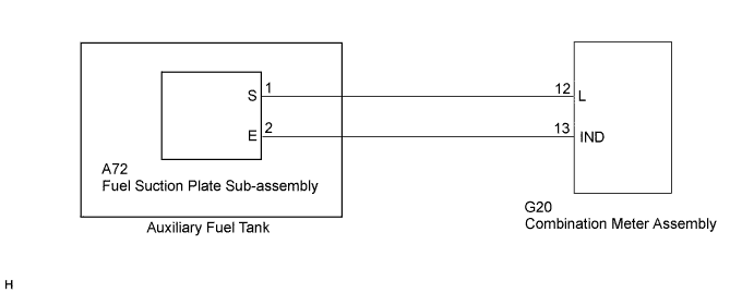
WIRING DIAGRAM
INSPECTION PROCEDURE
CHECK COMBINATION METER ASSEMBLY (OUTPUT VOLTAGE)
CHECK HARNESS AND CONNECTOR (COMBINATION METER ASSEMBLY - FUEL SUCTION PLATE SUB-ASSEMBLY)
INSPECT FUEL SUCTION PLATE SUB-ASSEMBLY
CHECK HARNESS AND CONNECTOR (COMBINATION METER - FUEL SUCTION PLATE SUB-ASSEMBLY)
METER / GAUGE SYSTEM - Auxiliary Fuel Tank Warning Light Circuit |
DESCRIPTION
When fuel with a high percentage of alcohol is used, cold startability will decline because alcohol is difficult to vaporize at low temperatures such as 20°C (68°F) or less. In order to enhance cold startability, a sub-injection system, which consists of the auxiliary fuel tank with a capacity of 600 cc, sub-pump, and solenoid valve, is used on these vehicles.The meter CPU determines the fuel level in the auxiliary fuel tank using a thermistor that is located in the auxiliary fuel tank.The thermistor is installed at a height that corresponds to 100 cc (6.1 cu.in.) of fuel remaining in the tank. The cup that the thermistor is mounted in has holes to allow the fuel to enter and leave the area around the thermistor. As a result, the location of the thermistor is maintained in relation to the actual fuel level.The meter CPU supplies battery voltage to the thermistor. The resistance of the thermistor in the auxiliary fuel tank depends on whether the thermistor is immersed in fuel. When the thermistor is not immersed in fuel, the resistance value decreases as the thermistor generates heat.The meter CPU detects the voltage between G20-12 (L) and G20-13 (IND). When the voltage between G20-12 (L) and G20-13 (IND) is below 6.5 V, the meter CPU illuminates the auxiliary fuel tank warning light.- NOTICE:
- When the temperature inside the auxiliary fuel tank is not between -10°C and 80°C (14°F and 176°F), the auxiliary fuel tank warning light may not operate normally. As a result, the combination meter will only operate the auxiliary fuel tank warning light within 400 seconds after the ignition switch is turned ON.
- HINT:
- This circuit is only for Flexible Fuel Vehicles (FFV).
- The auxiliary fuel tank may be unnecessary in a warm climate because its purpose is to enhance cold startability. As a result, some drivers may not wish to make use of the auxiliary fuel tank. Therefore, it is possible for the driver to disable the auxiliary fuel tank warning light. Due to the possibility of the warning having been disabled, check the auxiliary fuel tank warning light setting before inspecting this circuit (HILUX_TGN26 RM000004DIQ00SX.html).
- A bulb check is not performed for the auxiliary fuel tank warning light.
- When the fuel level in the auxiliary fuel tank falls below 100 cc (6.1 cu.in.), the auxiliary fuel tank warning light comes on.
- The auxiliary fuel tank must be replaced if the thermistor malfunctions. The thermistor is not available separately.
WIRING DIAGRAM
INSPECTION PROCEDURE
- HINT:
- Check the auxiliary fuel tank warning light setting (HILUX_TGN26 RM000004DIQ00SX.html).
| 1.CHECK COMBINATION METER ASSEMBLY (OUTPUT VOLTAGE) |
Disconnect the A72 fuel suction plate sub-assembly connector.
Measure the voltage according to the value(s) in the table below.
- Standard Voltage:
Tester Connection
| Condition
| Specified Condition
|
A72-1 (S) - Body ground
| Ignition switch ON
| 11 to 14 V
|
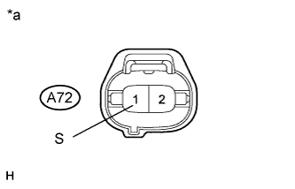
Text in Illustration*a
| Front view of wire harness connector
(to Auxiliary Fuel Tank)
|
| 2.CHECK HARNESS AND CONNECTOR (COMBINATION METER ASSEMBLY - FUEL SUCTION PLATE SUB-ASSEMBLY) |
Disconnect the G20 combination meter assembly connector.
Measure the resistance according to the value(s) in the table below.
- Standard Resistance:
Tester Connection
| Condition
| Specified Condition
|
G20-13 (IND) - A72-2 (E)
| Always
| Below 1 Ω
|
G20-13 (IND) - Body ground
| Always
| 10 kΩ or higher
|
| | REPAIR OR REPLACE HARNESS OR CONNECTOR |
|
|
| 3.INSPECT FUEL SUCTION PLATE SUB-ASSEMBLY |
Reconnect the A72 fuel suction plate sub-assembly and G20 combination meter assembly connector.
Measure the voltage according to the value(s) in the table below.
- Standard Voltage:
Tester Connection
| Condition
| Specified Condition
|
G20-12 (L) - G20-13 (IND)
| Ignition switch ON, auxiliary tank is empty (Auxiliary tank warning light comes on)
| Below 6.5 V
|
G20-12 (L) - G20-13 (IND)
| Ignition switch ON, auxiliary tank is full (Auxiliary tank warning light goes off)
| 6.6 V or higher
|
- HINT:
- If the result is not as specified, the whole fuel suction plate sub-assembly should be replaced if the thermistor has a malfunction because this part is not independently supplied.
Text in Illustration*a
| Component with harness connected
(Combination Meter Assembly)
|
| 4.CHECK HARNESS AND CONNECTOR (COMBINATION METER - FUEL SUCTION PLATE SUB-ASSEMBLY) |
Disconnect the G20 combination meter assembly connector.
Measure the resistance according to the value(s) in the table below.
- Standard Resistance:
Tester Connection
| Condition
| Specified Condition
|
G20-12 (L) - A72-1 (S)
| Always
| Below 1 Ω
|
G20-12 (L) - Body ground
| Always
| 10 kΩ or higher
|
| | REPAIR OR REPLACE HARNESS OR CONNECTOR |
|
|