REMOVE STEERING PAD SWITCH ASSEMBLY (w/ Multi-information Display)
REMOVE STEERING PAD SWITCH LH (w/o Multi-information Display)
REMOVE NO. 2 STEERING WHEEL ORNAMENT (w/o Steering Pad Switch)
REMOVE NO. 1 STEERING WHEEL ORNAMENT (w/o Steering Pad Switch)
REMOVE CRUISE CONTROL MAIN SWITCH (w/ Cruise Control System)
Steering Wheel -- Removal |
- CAUTION:
- Some of these service operations affect the SRS. Read the precautionary notices concerning the SRS before servicing (HILUX_TGN26 RM000000KT10GEX.html).
| 1. PLACE FRONT WHEELS FACING STRAIGHT AHEAD |
| 2. DISCONNECT CABLE FROM NEGATIVE BATTERY TERMINAL |
- CAUTION:
- Wait at least 90 seconds after disconnecting the cable from the negative (-) battery terminal to disable the SRS system.
- NOTICE:
- When disconnecting the cable, some systems need to be initialized after the cable is reconnected (HILUX_TGN26 RM000004QR3009X.html).
| 3. REMOVE STEERING PAD ASSEMBLY (for 3 Spoke) |
Remove the screw.
 |
Detach the 3 pins and remove the steering pad.
 |
Disconnect the horn wire.
| 4. REMOVE STEERING PAD (for 4 Spoke) |
| 5. REMOVE STEERING PAD SWITCH ASSEMBLY (w/ Multi-information Display) |
Disconnect the connectors and detach the 2 clamps.
Text in Illustration *1 Pin *2 Clamp
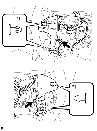 |
Remove the 2 screws.
Detach the 4 pins and remove the steering pad switch.
| 6. REMOVE STEERING PAD SWITCH LH (w/o Multi-information Display) |
- HINT:
- Refer to the step "REMOVE STEERING PAD SWITCH ASSEMBLY".
| 7. REMOVE NO. 2 STEERING WHEEL ORNAMENT (w/o Steering Pad Switch) |
Remove the screw.
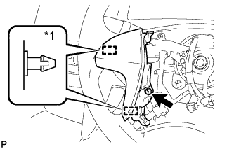 |
Detach the 2 pins and remove the steering wheel ornament.
Text in Illustration *1 Pin
| 8. REMOVE NO. 1 STEERING WHEEL ORNAMENT (w/o Steering Pad Switch) |
Remove the screw.
 |
Detach the 2 pins and remove the steering wheel ornament.
Text in Illustration *1 Pin
| 9. REMOVE CRUISE CONTROL MAIN SWITCH (w/ Cruise Control System) |
Disconnect the connector.
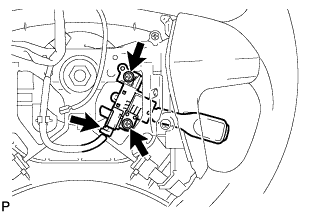 |
Remove the 2 screws.
Remove the switch as shown in the illustration.
 |
| 10. REMOVE STEERING WHEEL ASSEMBLY |
Remove the steering wheel assembly set nut.
Put matchmarks on the steering wheel assembly and steering main shaft.
Text in Illustration *A for 3 Spoke *B for 4 Spoke *1 Matchmark *a Turn *b Hold
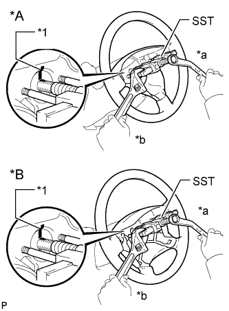 |
Using SST, remove the steering wheel assembly.
- SST
- 09950-50013(09951-05010,09952-05010,09953-05020,09954-05021)
- NOTICE:
- Apply a small amount of grease to the threads and tip of SST (09953-05020) before use.