DESCRIPTION
CONFIRMATION DRIVING PATTERN
WIRING DIAGRAM
INSPECTION PROCEDURE
CHECK FOR ANY OTHER DTCS OUTPUT (IN ADDITION TO DTC P2A00)
INSPECT AIR FUEL RATIO SENSOR (HEATER RESISTANCE)
CHECK HARNESS AND CONNECTOR (AIR FUEL RATIO SENSOR - ECM)
PERFORM CONFIRMATION DRIVING PATTERN
CHECK WHETHER DTC OUTPUT RECURS (DTC P2A00)
REPLACE AIR FUEL RATIO SENSOR
PERFORM CONFIRMATION DRIVING PATTERN
CHECK WHETHER DTC OUTPUT RECURS (DTC P2A00)
DTC P2A00 A/F Sensor Circuit Slow Response (Bank 1 Sensor 1) |
DESCRIPTION
- HINT:
- Sensor 1 refers to the sensor mounted in front of the Three Way Catalytic Converter (TWC) and located near the engine assembly.
Refer to DTC P2195 (HILUX_TGN26 RM000000WC40R3X_01.html).DTC No.
| DTC Detection Condition
| Trouble Area
|
P2A00
| The calculated value of the air fuel ratio sensor response rate deterioration level is less than the threshold (2 trip detection logic).
| - Air fuel ratio sensor
- ECM
|
CONFIRMATION DRIVING PATTERN
- HINT:
- Performing this confirmation driving pattern will activate the air fuel ratio sensor response monitor.
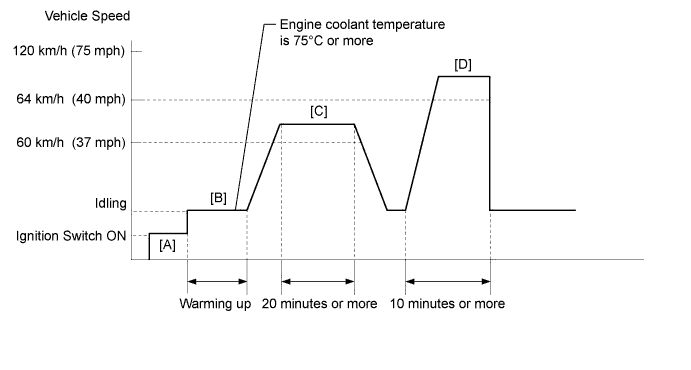
- Connect the intelligent tester to the DLC3.
- Turn the ignition switch to ON and turn the intelligent tester on [A].
- Enter the following menus: Powertrain / Engine and ECT / DTC / Clear.
- Clear DTCs.
- Start the engine and warm it up until the engine coolant temperature is 75°C (167°F) or higher [B].
- Drive the vehicle at 60 km/h (37 mph) or more for 20 minutes or more [C].
- CAUTION:
- When performing the confirmation driving pattern, obey all speed limits and traffic laws.
- HINT:
- This step is performed to complete ethanol concentration learning.
- If DTC P2A00 is output when any of the following conditions is met, it is necessary to complete ethanol concentration learning to meet preconditions.
- The battery has been disconnected and reconnected.
- The DTCs have been cleared.
- Both fuel tank assemblies (main and sub tanks) have been filled with fuel.
- Drive the vehicle at a constant speed between 64 km/h and 120 km/h (40 mph and 75 mph) for 10 minutes or more [D].
- Turn the ignition switch off.
- Repeat steps [B] and [D] above.
- Enter the following menus: Powertrain / Engine and ECT / DTC.
- Check if any DTCs (any pending DTCs) are output.
WIRING DIAGRAM
Refer to DTC P2195 (HILUX_TGN26 RM000000WC40R3X_07.html).
INSPECTION PROCEDURE
- HINT:
- Intelligent tester only:
- Malfunctioning areas can be identified by performing the "Control the Injection Volume for A/F Sensor" function provided in the Active Test. The "Control the Injection Volume for A/F Sensor" function can help determine whether the air fuel ratio sensor, heated oxygen sensor and other potential trouble areas are malfunctioning.
The following instructions describe how to conduct the "Control the Injection Volume for A/F Sensor" operation using the intelligent tester.- Connect the intelligent tester to the DLC3.
- Start the engine.
- Turn the tester on.
- Warm up the engine at an engine speed of 2500 rpm for approximately 90 seconds.
- Enter the following menus: Powertrain / Engine and ECT / Active Test / Control the Injection Volume for A/F Sensor.
- Perform the "Control the Injection Volume for A/F Sensor" operation with the engine idling (press the RIGHT or LEFT button to change the fuel injection volume).
- Monitor the output voltages of the air fuel ratio and heated oxygen sensors (AFS Voltage B1S1 and O2S B1S2) displayed on the tester.
- HINT:
- The "Control the Injection Volume for A/F Sensor" operation lowers the fuel injection volume by 12.5% or increases the injection volume by 12.5%.
- The sensors react in accordance with increases and decreases in the fuel injection volume.
- Standard:
Tester Display
(Sensor)
| Injection Volume
| Status
| Voltage
|
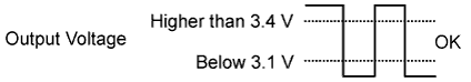
AFS Voltage B1S1
(Air fuel ratio sensor)
| +12.5%
| Rich
| Below 3.1 V
|
-12.5%
| Lean
| Higher than 3.4 V
|
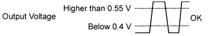
O2S B1S2
(Heated oxygen sensor)
| +12.5%
| Rich
| Higher than 0.55 V
|
-12.5%
| Lean
| Below 0.4 V
|
- NOTICE:
- The air fuel ratio sensor has an output delay of a few seconds and the heated oxygen sensor (sensor 2) output has a maximum output delay of approximately 20 seconds.
Case
| Air Fuel Ratio Sensor (Sensor 1) Output Voltage
| Heated Oxygen Sensor (Sensor 2) Output Voltage
| Main Suspected Trouble Area
|
1
| 
|
| -
|
2
|

|
| - Air fuel ratio sensor
- Air fuel ratio sensor heater
- Air fuel ratio sensor circuit
|
3
|
|
| - Heated oxygen sensor
- Heated oxygen sensor heater
- Heated oxygen sensor circuit
|
4
|
|
| - Fuel injector assembly
- Fuel pressure
- Gas leak from exhaust system (air-fuel ratio extremely rich or lean)
|
- Following the "Control the Injection Volume for A/F Sensor" procedure enables technicians to check and graph the voltage outputs of both the air fuel ratio and heated oxygen sensors.
- To display the graph, enter the following menus: Powertrain / Engine and ECT / Active Test / Control the Injection Volume for A/F Sensor / View / AFS Voltage B1S1 and O2S B1S2.
- HINT:
- Read freeze frame data using the intelligent tester. Freeze frame data records the engine condition when malfunctions are detected. When troubleshooting, freeze frame data can help determine if the vehicle was moving or stationary, if the engine was warmed up or not, if the air fuel ratio was lean or rich, and other data from the time the malfunction occurred.
- A low air fuel ratio sensor voltage could be caused by a rich air fuel mixture. Check for conditions that would cause the engine to run rich.
- A high air fuel ratio sensor voltage could be caused by a lean air fuel mixture. Check for conditions that would cause the engine to run lean.
- NOTICE:
- Inspect the fuses for circuits related to this system before performing the following inspection procedure.
| 1.CHECK FOR ANY OTHER DTCS OUTPUT (IN ADDITION TO DTC P2A00) |
Connect the intelligent tester to the DLC3.
Turn the ignition switch to ON.
Turn the tester on.
Enter the following menus: Powertrain / Engine and ECT / DTC.
Read DTCs.
ResultResult
| Proceed to
|
DTC P2A00 is output
| A
|
DTC P2A00 and other DTCs are output
| B
|
- HINT:
- If any DTCs relating to the A/F sensor (DTCs for the A/F sensor heater or A/F sensor admittance) are output, troubleshoot those DTCs first.
| 2.INSPECT AIR FUEL RATIO SENSOR (HEATER RESISTANCE) |
Inspect the air fuel ratio sensor (HILUX_TGN26 RM000001421010X.html).
| 3.CHECK HARNESS AND CONNECTOR (AIR FUEL RATIO SENSOR - ECM) |
Disconnect the air fuel ratio sensor connector.
Measure the voltage according to the value(s) in the table below.
- Standard Voltage:
Tester Connection
| Switch Condition
| Specified Condition
|
C85-2 (+B) - Body ground
| Ignition switch ON
| 11 to 14 V
|
Turn the ignition switch off.
Disconnect the ECM connector.
Measure the resistance according to the value(s) in the table below.
- Standard Resistance (Check for Open):
Tester Connection
| Condition
| Specified Condition
|
C85-3 (A1A+) - C97-7 (A1A+)
| Always
| Below 1 Ω
|
C85-4 (A1A-) - C97-1 (A1A-)
| Always
| Below 1 Ω
|
C85-1 (HA1A) - C97-6 (HA1A)
| Always
| Below 1 Ω
|
- Standard Resistance (Check for Short):
Tester Connection
| Condition
| Specified Condition
|
C85-3 (A1A+) or C97-7 (A1A+) - Body ground
| Always
| 10 kΩ or higher
|
C85-4 (A1A-) or C97-1 (A1A-) - Body ground
| Always
| 10 kΩ or higher
|
C85-1 (HA1A) or C97-6 (HA1A) - Body ground
| Always
| 10 kΩ or higher
|
Reconnect the ECM connector.
Reconnect the air fuel ratio sensor connector.
| | REPAIR OR REPLACE HARNESS OR CONNECTOR |
|
|
| 4.PERFORM CONFIRMATION DRIVING PATTERN |
| 5.CHECK WHETHER DTC OUTPUT RECURS (DTC P2A00) |
Connect the intelligent tester to the DLC3.
Turn the ignition switch to ON.
Turn the tester on.
Enter the following menus: Powertrain / Engine and ECT / DTC.
Read DTCs.
ResultResult
| Proceed to
|
DTC P2A00 is output
| A
|
DTC is not output
| B
|
| 6.REPLACE AIR FUEL RATIO SENSOR |
Replace the air fuel ratio sensor (HILUX_TGN26 RM00000142300ZX.html).
| 7.PERFORM CONFIRMATION DRIVING PATTERN |
| 8.CHECK WHETHER DTC OUTPUT RECURS (DTC P2A00) |
Connect the intelligent tester to the DLC3.
Turn the ignition switch to ON.
Turn the tester on.
Enter the following menus: Powertrain / Engine and ECT / DTC.
Read DTCs.
ResultResult
| Proceed to
|
DTC is not output
| A
|
DTC P2A00 is output
| B
|