Exhaust Manifold -- Installation |
| 1. INSTALL AIR FUEL RATIO SENSOR (for Bank 2 Sensor 1) |
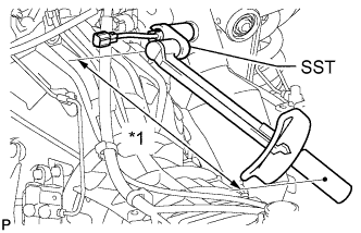
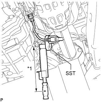
Using SST, install the air fuel ratio sensor.
- SST
- 09224-00010
- Torque:
- without SST:
- 44 N*m{449 kgf*cm, 32 ft.*lbf}
- with SST:
- 40 N*m{408 kgf*cm, 30 ft.*lbf}
Text in Illustration *1 Fulcrum Length - HINT:
- Use a torque wrench with a fulcrum length of 30 cm (11.8 in.). When using a torque wrench with a fulcrum length that is not 30 cm (11.8 in.), calculate the torque specification for the torque wrench and SST based on the "without SST" torque specification (HILUX_TGN26 RM000004QR1006X.html).
- Make sure SST and the wrench are connected in a straight line.
 |
Connect the air fuel ratio sensor connector.
| 2. INSTALL EXHAUST MANIFOLD SUB-ASSEMBLY LH |
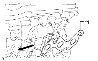
Install a new gasket to the cylinder head LH with the oval shape facing rearward.
Text in Illustration *1 Oval Shape 
Forward - NOTICE:
- Make sure the gasket is installed facing the proper direction.
 |
Install the exhaust manifold with 6 new nuts.
- Torque:
- 21 N*m{214 kgf*cm, 15 ft.*lbf}
Connect the air fuel ratio sensor connector.
| 3. INSTALL NO. 2 MANIFOLD STAY |
Install the No. 2 manifold stay with the 3 bolts.
- Torque:
- 40 N*m{408 kgf*cm, 30 ft.*lbf}
| 4. INSTALL AIR FUEL RATIO SENSOR (for Bank 1 Sensor 1) |
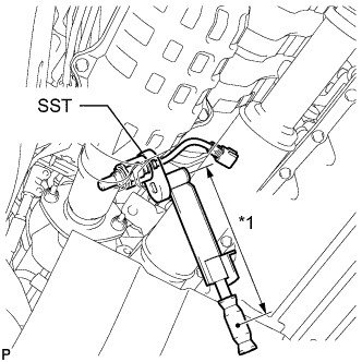
Using SST, install the air fuel ratio sensor.
- SST
- 09224-00010
- Torque:
- without SST:
- 44 N*m{449 kgf*cm, 32 ft.*lbf}
- with SST:
- 40 N*m{408 kgf*cm, 30 ft.*lbf}
Text in Illustration *1 Fulcrum Length - HINT:
- Use a torque wrench with a fulcrum length of 30 cm (11.8 in.). When using a torque wrench with a fulcrum length that is not 30 cm (11.8 in.), calculate the torque specification for the torque wrench and SST based on the "without SST" torque specification (HILUX_TGN26 RM000004QR1006X.html).
- Make sure SST and the wrench are connected in a straight line.
 |
Connect the air fuel ratio sensor connector.
| 5. INSTALL EXHAUST MANIFOLD SUB-ASSEMBLY RH |
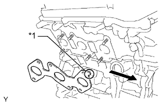
Install a new gasket to the cylinder head RH with the oval shape facing forward.
Text in Illustration *1 Oval Shape Forward - NOTICE:
- Make sure the gasket is installed facing the proper direction.
 |
Install the exhaust manifold with 6 new nuts.
- Torque:
- 21 N*m{214 kgf*cm, 15 ft.*lbf}
Connect the air fuel ratio sensor connector.
| 6. INSTALL MANIFOLD STAY |
Install the manifold stay with the 3 bolts.
- Torque:
- 40 N*m{408 kgf*cm, 30 ft.*lbf}
| 7. INSTALL FRONT EXHAUST PIPE ASSEMBLY |
Connect the front exhaust pipe to the exhaust pipe support.
Install a new gasket to the end of the front exhaust pipe that connects to the exhaust manifold.
- NOTICE:
- Do not reuse the gasket.
Connect the front exhaust pipe to the exhaust manifold with the 2 nuts.
- Torque:
- 54 N*m{554 kgf*cm, 40 ft.*lbf}
Using a vernier caliper, measure the free length of the compression spring.
- Minimum length:
- 40.5 mm (1.59 in.)
 |
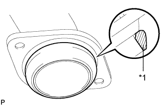
Install a new gasket to the end of the front exhaust pipe that connects to the center exhaust pipe.
Text in Illustration *1 Gasket - NOTICE:
- Be sure to install the gasket so that it faces the correct direction.
- Do not reuse the gasket.
- When connecting the exhaust pipe, do not push in the gasket with the exhaust pipe.
- HINT:
- Using a plastic-faced hammer, uniformly tap the gasket so that the gasket and front exhaust pipe fit properly.
 |
Connect the front exhaust pipe to the center exhaust pipe and 2 compression springs with the 2 bolts.
- Torque:
- 43 N*m{438 kgf*cm, 32 ft.*lbf}
| 8. INSTALL FRONT NO. 2 EXHAUST PIPE ASSEMBLY |
Connect the front No. 2 exhaust pipe to the exhaust pipe support.
Install 2 new gaskets.
- NOTICE:
- Do not reuse the gaskets.
Install the front No. 2 exhaust pipe with 2 new nuts to the exhaust manifold.
- Torque:
- 54 N*m{554 kgf*cm, 40 ft.*lbf}
Connect the front No. 2 exhaust pipe with the 2 bolts and 2 new nuts to the front No. 2 exhaust pipe.
- Torque:
- 48 N*m{489 kgf*cm, 35 ft.*lbf}
| 9. INSTALL HEATED OXYGEN SENSOR (for Bank 1 Sensor 2) |
Using SST, install the heated oxygen sensor.
- SST
- 09224-00010
- Torque:
- without SST:
- 44 N*m{449 kgf*cm, 32 ft.*lbf}
- with SST:
- 40 N*m{408 kgf*cm, 30 ft.*lbf}
Text in Illustration *1 Fulcrum Length - HINT:
- Use a torque wrench with a fulcrum length of 30 cm (11.8 in.). When using a torque wrench with a fulcrum length that is not 30 cm (11.8 in.), calculate the torque specification for the torque wrench and SST based on the "without SST" torque specification (HILUX_TGN26 RM000004QR1006X.html).
- Make sure SST and the wrench are connected in a straight line.
 |
Connect the heated oxygen sensor connector.
| 10. INSTALL HEATED OXYGEN SENSOR (for Bank 2 Sensor 2) |
Using SST, install the heated oxygen sensor.
- SST
- 09224-00010
- Torque:
- without SST:
- 44 N*m{449 kgf*cm, 32 ft.*lbf}
- with SST:
- 40 N*m{408 kgf*cm, 30 ft.*lbf}
Text in Illustration *1 Fulcrum Length - HINT:
- Use a torque wrench with a fulcrum length of 30 cm (11.8 in.). When using a torque wrench with a fulcrum length that is not 30 cm (11.8 in.), calculate the torque specification for the torque wrench and SST based on the "without SST" torque specification (HILUX_TGN26 RM000004QR1006X.html).
- Make sure SST and the wrench are connected in a straight line.
 |
Connect the heated oxygen sensor connector.
| 11. INSPECT FOR EXHAUST GAS LEAK |
| 12. INSTALL FRONT FENDER APRON SEAL UPPER LH |
Install the fender apron seal upper LH with the 5 clips.
| 13. INSTALL FRONT FENDER SEAL LH |
Install the fender seal LH with the 5 clips.
| 14. INSTALL FRONT FENDER APRON SEAL UPPER RH |
Install the fender apron seal upper RH with the 5 clips.
| 15. INSTALL FRONT FENDER SEAL RH |
Install the fender seal RH with the 5 clips.