CHECK FOR ANY OTHER DTCS OUTPUT (IN ADDITION TO P0046)
CHECK TURBOCHARGER SUB-ASSEMBLY (DC MOTOR OPERATION)
INSPECT TURBOCHARGER SUB-ASSEMBLY (DC MOTOR RESISTANCE)
CHECK HARNESS AND CONNECTOR (DC MOTOR - TURBO MOTOR DRIVER)
CHECK WHETHER DTC OUTPUT RECURS (DTC P0046)
REPLACE TURBOCHARGER SUB-ASSEMBLY
REPAIR OR REPLACE HARNESS OR CONNECTOR
CONFIRM WHETHER MALFUNCTION HAS BEEN SUCCESSFULLY REPAIRED
DTC P0046 Turbocharger / Supercharger Boost Control Solenoid Circuit Range / Performance |
DESCRIPTION
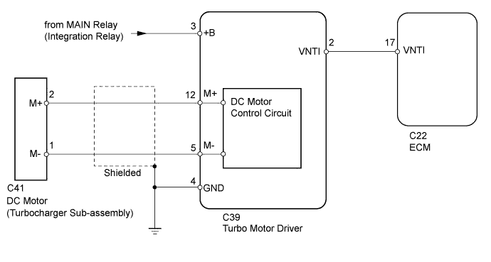
Variable nozzle vane type turbocharger consists primarily of a compressor wheel, turbine wheel, nozzle vane, unison ring, DC motor and nozzle vane position sensor.The ECM outputs a signal to the turbo motor driver, which actuates the DC motor, to control the nozzle vane position.
| DTC Detection Drive Pattern | DTC Detection Condition | Trouble Area |
| Drive the vehicle with a city driving pattern at least 10 minutes. | Either of following conditions met:
|
|
WIRING DIAGRAM
INSPECTION PROCEDURE
- HINT:
- Read freeze frame data using the intelligent tester. Freeze frame data records the engine condition when malfunctions are detected. When troubleshooting, freeze frame data can help determine if the vehicle was moving or stationary, if the engine was warmed up or not, and other data from the time the malfunction occurred.
| 1.CHECK FOR ANY OTHER DTCS OUTPUT (IN ADDITION TO P0046) |
Connect the intelligent tester to the DLC3.
Turn the ignition switch to ON and turn the tester on.
Enter the following menus: Powertrain / Engine and ECT / DTC.
Read the DTCs.
Result Result Proceed to P0046 is output A P0046 and other DTCs are output B - HINT:
- If any DTCs other than P0046 are output, troubleshoot those DTCs first.
|
| ||||
| A | |
| 2.CHECK TURBOCHARGER SUB-ASSEMBLY (DC MOTOR OPERATION) |
Turn the ignition switch to ON.
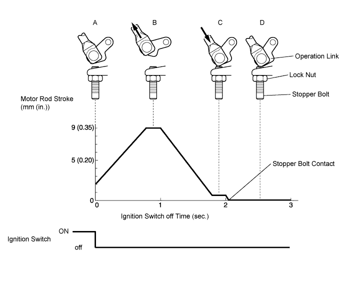
Turn the ignition switch off and check the DC motor operation (check the operation link movement).
- HINT:
- When it is necessary to repeat this inspection, wait 30 seconds or more with the ignition switch off before performing the inspection.
- OK:
- When ignition switch is turned off, operation link moves as shown in A through D in illustration below.
- Operation link and motor rod move smoothly when moving from position shown in A to that shown in B, and from position shown in B to that shown in C.
|
| ||||
| OK | ||
| ||
| 3.CHECK TURBO MOTOR DRIVER |
Voltage Inspection
Turn the ignition switch to ON.
Measure the voltage according to the value(s) in the table below.
- Standard Voltage:
Tester Connection Condition Specified Condition C39-3 (+B) - C39-4 (GND) Always 11 to 14 V
Text in Illustration *a Component with harness connected
(Turbo Motor Driver)

Output Waveform Inspection
Turn the ignition switch to ON.
Check the waveform of the ECM connectors using an oscilloscope.
- OK:
Tester Connection Switch Condition Specified Condition C39-2 (VNTI) - C39-4 (GND) Ignition switch ON Correct waveform is as shown
Text in Illustration *a Component with harness connected
(Turbo Motor Driver)

|
| ||||
| OK | |
| 4.INSPECT TURBOCHARGER SUB-ASSEMBLY (DC MOTOR RESISTANCE) |
Disconnect the DC motor connector.
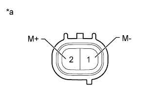 |
Measure the DC motor resistance.
- Standard resistance:
- 1 to 100 Ω
Text in Illustration *a Component without harness connected
(DC Motor)
|
| ||||
| OK | |
| 5.CHECK HARNESS AND CONNECTOR (DC MOTOR - TURBO MOTOR DRIVER) |
Disconnect the DC motor connector.
Disconnect the turbo motor driver connector.
Measure the resistance according to the value(s) in the table below.
- Standard Resistance:
Tester Connection Condition Specified Condition C39-12 (M+) - C41-2 (M+) Always Below 1 Ω C39-5 (M-) - C41-1 (M-) Always Below 1 Ω C39-12 (M+) or C41-2 (M+) - Body ground Always 10 kΩ or higher C39-5 (M-) or C41-1 (M-) - Body ground Always 10 kΩ or higher
Reconnect the turbo motor driver connector.
Reconnect the DC motor connector.
|
| ||||
| OK | |
| 6.CHECK WHETHER DTC OUTPUT RECURS (DTC P0046) |
Connect the intelligent tester to the DLC3.
Turn the ignition switch to ON and turn the tester on.
Clear the DTCs (HILUX_TGN26 RM000000PDK0XCX.html).
Turn the ignition switch off.
Remove the EFI fuse from the engine room relay block and junction block assembly for more than 1 minute.
Turn the ignition switch to ON and wait for 10 seconds or more.
Start the engine.
Drive the vehicle with a city driving pattern at least 10 minutes.
Enter the following menus: Powertrain / Engine and ECT / DTC.
Read the DTCs.
Result Result Proceed to P0046 is output A No DTC is output B
|
| ||||
| A | ||
| ||
| 7.REPLACE TURBOCHARGER SUB-ASSEMBLY |
Replace turbocharger sub-assembly (HILUX_TGN26 RM00000143U013X.html).
|
| ||||
| 8.REPLACE TURBO MOTOR DRIVER |
Replace turbo motor driver (HILUX_TGN26 RM000004QB2006X.html).
|
| ||||
| 9.REPAIR OR REPLACE HARNESS OR CONNECTOR |
Repair or replace the harness or connector.
| NEXT | |
| 10.CONFIRM WHETHER MALFUNCTION HAS BEEN SUCCESSFULLY REPAIRED |
Connect the intelligent tester to the DLC3.
Turn the ignition switch to ON and turn the tester on.
Clear the DTCs (HILUX_TGN26 RM000000PDK0XCX.html).
Turn the ignition switch off.
Remove the EFI fuse from the engine room relay block and junction block assembly for more than 1 minute.
Turn the ignition switch to ON and wait for 10 seconds or more.
Start the engine.
Drive the vehicle with a city driving pattern at least 10 minutes.
Enter the following menus: Powertrain / Engine and ECT / DTC.
Confirm that the DTC is not output again.
| NEXT | ||
| ||