Vehicle Interior. Hilux. Tgn26, 36 Kun25, 26, 35, 36 Ggn25
Heating Air Conditioning. Hilux. Tgn26, 36 Kun25, 26, 35, 36 Ggn25
Air Conditioning System (For Manual Air Conditioning System) -- Terminals Of Ecu |
| CHECK AIR CONDITIONING AMPLIFIER ASSEMBLY |

Disconnect the G34 air conditioning amplifier assembly connector.
Measure the voltage and resistance according to the value(s) in the table below.
Terminal No. (Symbol) Wiring Color Terminal Description Condition Specified Condition G34-10 (IG+) - G34-18 (GND) R-L - L Ignition power supply Ignition switch ON 11 to 14 V Ignition switch off Below 1 V G34-18 (GND) - Body ground L - Body ground Ground Always Below 1 Ω - If the result is not as specified, there may be a malfunction on the wire harness side.
- If the result is not as specified, there may be a malfunction on the wire harness side.
Reconnect the G34 air conditioning amplifier assembly connector.
Measure the voltage and resistance according to the value(s) in the table below.
Terminal No. (Symbol) Wiring Color Terminal Description Condition Specified Condition G34-1 (MGC) - G34-18 (GND) L-W - L Cooler compressor assembly operation signal - Engine idling
- Blower switch LO level
- Cooler switch off or cooler switch on (magnet clutch on not permitted)
11 to 14 V - Engine idling
- Blower switch LO level
- Cooler switch on (magnet clutch on permitted)
Below 1 V G34-2 (ACT) - G34-18 (GND) R-L - L Magnet clutch on permit signal - Engine idling
- Blower switch LO level
- Cooler switch on (magnet clutch on)
5 to 6 V - Engine idling
- Blower switch LO level
- Cooler switch off or on (magnet clutch off)
Below 1 V G34-3 (PSW) - G34-18 (GND) Y-B - L Air conditioner pressure sensor signal - Engine idling
- Refrigerant pressure normal
Below 1 V - Engine idling
- Refrigerant pressure abnormal (below 0.176 MPa [1.8 kgf/cm2, 25.5 psi] or higher than 3.025 MPa [30.9 kgf/cm2, 438.6 psi])
11 to 14 V G34-4 (ACON) - G34-18 (GND) R-G - L Cooler switch signal - Engine idling
- Blower switch LO level
- Cooler switch off
11 to 14 V - Engine idling
- Blower switch LO level
- Cooler switch on
Below 1 V G34-7 (TE) - G34-8 (SG-1) G - P No. 1 cooler thermistor signal - Ignition switch ON
- Evaporator temperature 0°C (32°F)
2.0 to 2.4 V - Ignition switch ON
- Evaporator temperature 15°C (59°F)
1.1 to 1.5 V G34-8 (SG-1) - Body ground P - Body ground Ground for No. 1 cooler thermistor Always Below 1 Ω G34-13 (IND-) - G34-18 (GND) R-L - L Cooler switch indicator signal - Engine idling
- Blower switch LO level
- Cooler switch off or cooler switch on
11 to 14 V - Engine idling
- Blower switch LO level
- Cooler switch on
Below 1 V G34-14 (AC1) - G34-18 (GND) Y - L Idle-up request signal - Engine idling
- Blower switch LO level
- Cooler switch off
11 to 14 V - Engine idling
- Blower switch LO level
- Cooler switch on
Below 1 V - If the result is not as specified, the air conditioning amplifier assembly may have a malfunction.
- Engine idling
| CHECK ECM (for 1KD-FTV, 2KD-FTV) |

Measure the voltage according to the value(s) in the table below.
If the result is not as specified, the ECM may have a malfunction.Terminal No. (Symbol) Wiring Color Terminal Description Condition Specified Condition G38-18 (AC1) - C23-7 (E1) Y - BR Idle-up request signal - Engine idling
- Blower switch on (LO level)
- Cooler switch on
Below 1 V - Engine idling
- Blower switch on (LO level)
- Cooler switch off
11 to 14 V G38-19 (ACT) - C23-7 (E1) R-L - BR Magnet clutch on permit output signal - Engine idling
- Blower switch on (LO level)
- Cooler switch off or on (magnet clutch off)
Below 1 V - Engine idling
- Blower switch on (LO level)
- Cooler switch on (magnet clutch on)
11 to 14 V - Engine idling
| CHECK ECM (for 2TR-FE) |

Measure the voltage according to the value(s) in the table below.
If the result is not as specified, the ECM may have a malfunction.Terminal No. (Symbol) Wiring Color Terminal Description Condition Specified Condition G88-24 (AC1) - C75-3 (E1) Y - BR Idle-up request signal - Engine idling
- Blower switch on (LO level)
- Cooler switch on
Below 1 V - Engine idling
- Blower switch on (LO level)
- Cooler switch off
11 to 14 V G88-25 (ACT) - C75-3 (E1) R-L - BR Magnet clutch on permit output signal - Engine idling
- Blower switch on (LO level)
- Cooler switch off or on (magnet clutch off)
Below 1 V - Engine idling
- Blower switch on (LO level)
- Cooler switch on (magnet clutch on)
11 to 14 V - Engine idling
| CHECK ECM (for 2TR-FBE) |
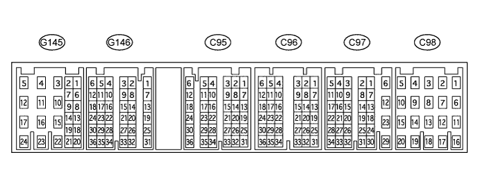
Measure the voltage according to the value(s) in the table below.
If the result is not as specified, the ECM may have a malfunction.Terminal No. (Symbol) Wiring Color Terminal Description Condition Specified Condition G146-19 (AC1) - C98-5 (E1) Y - BR Idle-up request signal - Engine idling
- Blower switch on (LO level)
- Cooler switch on
Below 1 V - Engine idling
- Blower switch on (LO level)
- Cooler switch off
11 to 14 V G146-21 (ACT) - C98-5 (E1) R-L - BR Magnet clutch on permit output signal - Engine idling
- Blower switch on (LO level)
- Cooler switch off or on (magnet clutch off)
Below 1 V - Engine idling
- Blower switch on (LO level)
- Cooler switch on (magnet clutch on)
11 to 14 V - Engine idling