Theft Deterrent System Horn Circuit
DESCRIPTION
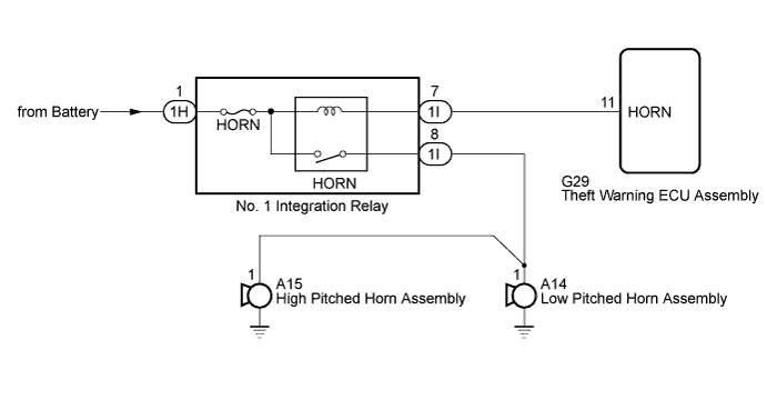
WIRING DIAGRAM
INSPECTION PROCEDURE
CHECK HORN ASSEMBLY
CHECK HARNESS AND CONNECTOR (THEFT WARNING ECU - NO. 1 INTEGRATION RELAY [HORN RELAY])
THEFT DETERRENT SYSTEM - Horn Circuit |
DESCRIPTION
When the theft deterrent system is changed from the armed state to the alarm sounding state, the theft warning ECU assembly turns on the HORN relay, causing the vehicle horn to sound at 0.4 seconds intervals.
WIRING DIAGRAM
INSPECTION PROCEDURE
- NOTICE:
- When replacing the theft warning ECU assembly, refer to the registration procedures (HILUX_TGN26 RM000000Z4Z01KX.html).
Press the horn switch and check if the horn sounds.
ResultResult
| Proceed to
|
Horn sounds
| A
|
Horn does not sound
| B
|
| 2.CHECK HARNESS AND CONNECTOR (THEFT WARNING ECU - NO. 1 INTEGRATION RELAY [HORN RELAY]) |
Disconnect the G29 theft warning ECU assembly connector.
Disconnect the 1I No. 1 integration relay connector.
Measure the resistance according to the value(s) in the table below.
- Standard Resistance:
Tester Connection
| Condition
| Specified Condition
|
G29-11 (HORN) - 1I-7
| Always
| Below 1 Ω
|
G29-11 (HORN) or 1I-7 - Body ground
| Always
| 10 kΩ or higher
|
| | REPAIR OR REPLACE HARNESS OR CONNECTOR |
|
|