Dtc 11 Room Temperature Sensor Circuit
DESCRIPTION
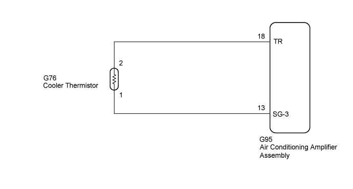
WIRING DIAGRAM
INSPECTION PROCEDURE
INSPECT COOLER THERMISTOR
CHECK AIR CONDITIONING AMPLIFIER ASSEMBLY
CHECK HARNESS AND CONNECTOR (AIR CONDITIONING AMPLIFIER - COOLER THERMISTOR)
DTC 11 Room Temperature Sensor Circuit |
DESCRIPTION
The cooler thermistor is installed in the instrument panel to detect the room temperature and control the heater and air conditioning AUTO function. The resistance of the cooler thermistor changes in accordance with the room temperature. As the temperature decreases, the resistance increases. As the temperature increases, the resistance decreases.The air conditioning amplifier assembly applies voltage (5 V) to the cooler thermistor and reads voltage changes as the resistance of the cooler thermistor changes.DTC Code
| DTC Detection Condition
| Trouble Area
|
11
| An open or short in the room temperature sensor circuit.
| - Cooler thermistor
- Air conditioning amplifier assembly
- Harness or connector
|
WIRING DIAGRAM
INSPECTION PROCEDURE
| 1.INSPECT COOLER THERMISTOR |
Remove the cooler thermistor (HILUX_TGN26 RM000001G9F01CX.html).
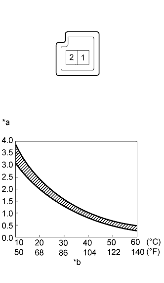
Measure the resistance according to the value(s) in the table below.
- Standard Resistance:
Tester Connection
| Condition
| Specified Condition
|
1 - 2
| 10°C (50°F)
| 3.00 to 3.73 kΩ
|
15°C (59°F)
| 2.45 to 2.88 kΩ
|
20°C (68°F)
| 1.95 to 2.30 kΩ
|
25°C (77°F)
| 1.60 to 1.80 kΩ
|
30°C (86°F)
| 1.28 to 1.47 kΩ
|
35°C (95°F)
| 1.00 to 1.22 kΩ
|
40°C (104°F)
| 0.80 to 1.00 kΩ
|
45°C (113°F)
| 0.65 to 0.85 kΩ
|
50°C (122°F)
| 0.50 to 0.70 kΩ
|
55°C (131°F)
| 0.44 to 0.60 kΩ
|
60°C (140°F)
| 0.36 to 0.50 kΩ
|
Text in Illustration*a
| Resistance (kΩ)
|
*b
| Temperature
|
- NOTICE:
- Even slightly touching the thermistor may change the resistance value. Be sure to hold the connector of the thermistor.
- When measuring the resistance, the thermistor temperature must be the same as the ambient temperature.
- HINT:
- As the temperature increases, the resistance decreases (Refer to the graph).
| 2.CHECK AIR CONDITIONING AMPLIFIER ASSEMBLY |
Remove the air conditioning amplifier assembly with its connectors still connected (HILUX_TGN26 RM000001K3A014X.html).
Measure the voltage according to the value(s) in the table below.
- Standard Voltage:
Tester Connection
| Condition
| Specified Condition
|
G95-18 (TR) - G95-13 (SG-3)
| - Ignition switch ON
- Cabin temperature 25°C (77°F)
| 1.8 to 2.2 V
|
- Ignition switch ON
- Cabin temperature 40°C (104°F)
| 1.2 to 1.6 V
|
Text in Illustration*a
| Component with harness connected
(Air Conditioning Amplifier Assembly)
|
- HINT:
- As the temperature increases, the voltage decreases.
ResultResult
| Proceed to
|
OK (When troubleshooting according to problem symptoms table.)
| A
|
OK (When troubleshooting according to DTC.)
| B
|
NG
| C
|
| 3.CHECK HARNESS AND CONNECTOR (AIR CONDITIONING AMPLIFIER - COOLER THERMISTOR) |
Disconnect the G95 air conditioning amplifier assembly connector.
Disconnect the G76 cooler thermistor connector.
Measure the resistance according to the value(s) in the table below.
- Standard Resistance:
Tester Connection
| Condition
| Specified Condition
|
G95-18 (TR) - G76-2
| Always
| Below 1 Ω
|
G95-13 (SG-3) - G76-1
|
G95-18 (TR) - Body ground
| Always
| 10 kΩ or higher
|
G95-13 (SG-3) - Body ground
|
| | REPAIR OR REPLACE HARNESS OR CONNECTOR |
|
|