Sfi System (W/O Secondary Air Injection System) Ecm Power Source Circuit
DESCRIPTION
WIRING DIAGRAM
INSPECTION PROCEDURE
CHECK NO. 1 INTEGRATION RELAY (POWER SOURCE)
INSPECT NO. 1 INTEGRATION RELAY (MAIN)
CHECK HARNESS AND CONNECTOR (NO. 1 INTEGRATION RELAY - ECM, BODY GROUND)
CHECK HARNESS AND CONNECTOR (ECM - BODY GROUND)
INSPECT ECM (IGSW VOLTAGE)
CHECK HARNESS AND CONNECTOR (ECM - IGNITION SWITCH ASSEMBLY)
INSPECT IGNITION SWITCH ASSEMBLY
SFI SYSTEM (w/o Secondary Air Injection System) - ECM Power Source Circuit |
DESCRIPTION
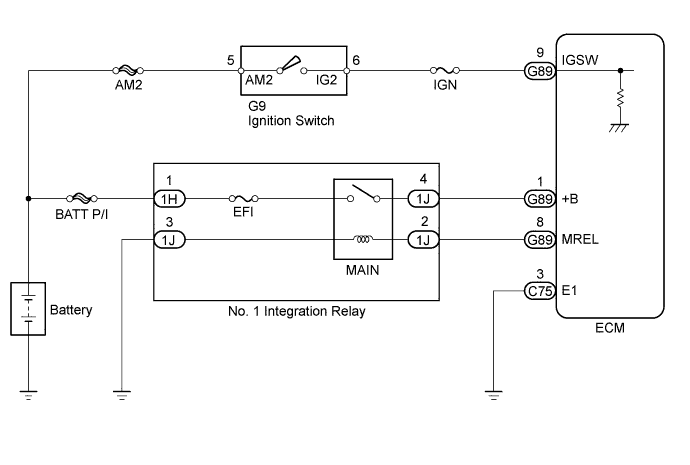
When the ignition switch is turned to ON, the battery voltage is applied to the IGSW terminal of the ECM. The output signal from the MREL terminal of the ECM causes a current to flow to the coil of the No. 1 integration relay (MAIN relay), closing the contacts and supplying power to terminals +B of the ECM.
WIRING DIAGRAM
INSPECTION PROCEDURE
- NOTICE:
- Inspect the fuses for circuits related to this system before performing the following inspection procedure.
| 1.CHECK NO. 1 INTEGRATION RELAY (POWER SOURCE) |
Remove the No. 1 integration relay from the engine room relay block and junction block.
Measure the voltage according to the value(s) in the table below.
- Standard Voltage:
Tester Connection
| Condition
| Specified Condition
|
1H-1 - Body ground
| Always
| 11 to 14 V
|
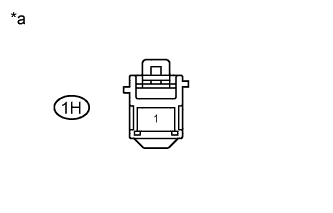
Text in Illustration*a
| Front view of wire harness connector
(to No. 1 Integration Relay)
|
| | REPAIR OR REPLACE HARNESS OR CONNECTOR (NO. 1 INTEGRATION RELAY - BATTERY) |
|
|
| 2.INSPECT NO. 1 INTEGRATION RELAY (MAIN) |
Inspect the No. 1 integration relay (MAIN) (HILUX_TGN26 RM000003BLB021X_01_0019.html).
| | REPLACE NO. 1 INTEGRATION RELAY |
|
|
| 3.CHECK HARNESS AND CONNECTOR (NO. 1 INTEGRATION RELAY - ECM, BODY GROUND) |
Check the harness and connectors between the No. 1 integration relay and ECM.
Remove the No. 1 integration relay from the engine room relay block and junction block.
Disconnect the ECM connector.
Measure the resistance according to the value(s) in the table below.
- Standard Resistance:
Tester Connection
| Condition
| Specified Condition
|
G89-8 (MREL) - 1J-2
| Always
| Below 1 Ω
|
G89-1 (+B) - 1J-4
| Always
| Below 1 Ω
|
G89-8 (MREL) or 1J-2 - Body ground
| Always
| 10 kΩ or higher
|
G89-1 (+B) or 1J-4 - Body ground
| Always
| 10 kΩ or higher
|
Check the harness and connectors between the No. 1 integration relay and body ground.
Measure the resistance according to the value(s) in the table below.
- Standard Resistance:
Tester Connection
| Condition
| Specified Condition
|
1J-3 - Body ground
| Always
| Below 1 Ω
|
| | REPAIR OR REPLACE HARNESS OR CONNECTOR |
|
|
| 4.CHECK HARNESS AND CONNECTOR (ECM - BODY GROUND) |
Disconnect the ECM connector.
Measure the resistance according to the value(s) in the table below.
- Standard Resistance:
Tester Connection
| Condition
| Specified Condition
|
C75-3 (E1) - Body ground
| Always
| Below 1 Ω
|
| | REPAIR OR REPLACE HARNESS OR CONNECTOR |
|
|
| 5.INSPECT ECM (IGSW VOLTAGE) |
Disconnect the ECM connectors.
Turn the ignition switch to ON.
Measure the voltage according to the value(s) in the table below.
- Standard Voltage:
Tester Connection
| Switch Condition
| Specified Condition
|
G89-9 (IGSW) - C75-3 (E1)
| Ignition switch ON
| 11 to 14 V
|
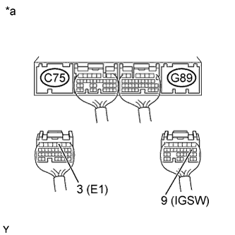
Text in Illustration*a
| Rear view of wire harness connector
(to ECM)
|
| 6.CHECK HARNESS AND CONNECTOR (ECM - IGNITION SWITCH ASSEMBLY) |
Disconnect the ECM connector.
Disconnect the ignition switch connector.
Measure the resistance according to the value(s) in the table below.
- Standard Resistance:
Tester Connection
| Condition
| Specified Condition
|
G9-6 (IG2) - G89-9 (IGSW)
| Always
| Below 1 Ω
|
G9-6 (IG2) or G89-9 (IGSW) - Body ground
| Always
| 10 kΩ or higher
|
| | REPAIR OR REPLACE HARNESS OR CONNECTOR |
|
|
| 7.INSPECT IGNITION SWITCH ASSEMBLY |
Inspect the ignition switch assembly (HILUX_TGN26 RM00000135X01BX.html).
| OK |
|
|
|
| REPAIR OR REPLACE HARNESS OR CONNECTOR (IGNITION SWITCH - BATTERY) |
|