DESCRIPTION
MONITOR DESCRIPTION
WIRING DIAGRAM
INSPECTION PROCEDURE
READ VALUE USING INTELLIGENT TESTER (EXHAUST TEMPERATURE)
READ VALUE USING INTELLIGENT TESTER (CHECK FOR OPEN IN WIRE HARNESS)
REPLACE EXHAUST GAS TEMPERATURE SENSOR
CHECK HARNESS AND CONNECTOR (EXHAUST GAS TEMPERATURE SENSOR - ECM)
REPLACE ECM
READ VALUE USING INTELLIGENT TESTER (CHECK FOR SHORT IN WIRE HARNESS)
REPLACE EXHAUST GAS TEMPERATURE SENSOR
CHECK HARNESS AND CONNECTOR (EXHAUST GAS TEMPERATURE SENSOR - ECM)
REPLACE ECM
REPAIR OR REPLACE HARNESS OR CONNECTOR
CONFIRM WHETHER MALFUNCTION HAS BEEN SUCCESSFULLY REPAIRED
DTC P0545 Exhaust Gas Temperature Sensor Circuit Low (Bank 1 Sensor 1) |
DTC P0546 Exhaust Gas Temperature Sensor Circuit High (Bank 1 Sensor 1) |
DTC P2032 Exhaust Gas Temperature Sensor Circuit Low (Bank 1 Sensor 2) |
DTC P2033 Exhaust Gas Temperature Sensor Circuit High (Bank 1 Sensor 2) |
DTC P242C Exhaust Gas Temperature Sensor Circuit Low Bank 1 Sensor 3 |
DTC P242D Exhaust Gas Temperature Sensor Circuit High Bank 1 Sensor 3 |
DESCRIPTION
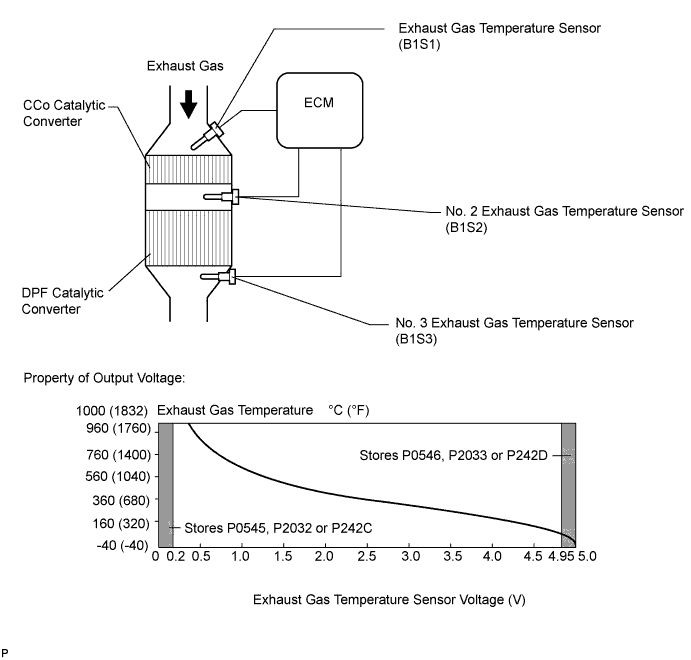
The exhaust gas temperature sensors are installed before and after the DPF catalytic converter to sense the exhaust gas temperature.A thermistor built into the sensor changes its resistance value according to the exhaust gas temperature. The lower the exhaust gas temperature, the higher the thermistor resistance value. The higher the exhaust gas temperature, the lower the thermistor resistance value.The exhaust gas temperature sensor is connected to the ECM. The 5 V power source voltage in the ECM is applied to the exhaust gas temperature sensor from terminal THCF (B1S1), THCI (B1S2) and THCO (B1S3) via resistor R.Resistor R and the exhaust gas temperature sensor are connected in series. When the resistance value of the exhaust gas temperature sensor changes in accordance with the exhaust gas temperature, the voltage at terminals THCF (B1S1), THCI (B1S2) and THCO (B1S3) also changes. The No. 1 exhaust gas temperature sensor monitors the temperature upstream of the CCo catalyst. The No. 2 exhaust gas temperature sensor monitors the temperature upstream of the DPF catalyst. The No. 3 exhaust gas temperature sensor monitors the rise in temperature of the DPF catalyst. When PM forced regeneration is needed, the ECM operates the exhaust fuel addition injector to obtain target upstream temperature of the DPF catalytic converter as monitored through sensor 2. In addition, the ECM monitors the temperature increase of the DPF catalytic converter using sensor 3.P0545DTC Detection Drive Pattern
| DTC Detection Condition
| Trouble Area
|
Idle the engine for 3 seconds after warming up the engine (the engine coolant temperature is 60°C (140°F) or higher) and allowing 11 minutes to elapse after starting the engine.
| Exhaust gas temperature sensor (B1S1) output voltage is below 0.2 V for 3 seconds or more when all conditions are met. (1 trip detection logic):
- After starting the engine, 11 minutes or more elapses
- Engine is running
- Coolant temperature is 60°C (140°F) or more
| - Open or short in exhaust gas temperature sensor (B1S1) circuit
- Exhaust gas temperature sensor (B1S1)
- ECM
|
P0546DTC Detection Drive Pattern
| DTC Detection Condition
| Trouble Area
|
Idle the engine for 3 seconds after warming up the engine (the engine coolant temperature is 60°C (140°F) or higher) and allowing 11 minutes to elapse after starting the engine.
| Exhaust gas temperature sensor (B1S1) output voltage is higher than 4.95 V for 3 seconds or more when all conditions are met. (1 trip detection logic):
- After starting the engine, 11 minutes or more elapses
- Engine is running
- Coolant temperature is 60°C (140°F) or more
| - Open or short in exhaust gas temperature sensor (B1S1) circuit
- Exhaust gas temperature sensor (B1S1)
- ECM
|
P2032DTC Detection Drive Pattern
| DTC Detection Condition
| Trouble Area
|
Idle the engine for 3 seconds after warming up the engine (the engine coolant temperature is 60°C (140°F) or higher) and allowing 11 minutes to elapse after starting the engine.
| No. 2 exhaust gas temperature sensor (B1S2) output voltage is below 0.2 V for 3 seconds or more when all conditions are met. (1 trip detection logic):
- After starting the engine, 11 minutes or more elapses
- Engine is running
- Coolant temperature is 60°C (140°F) or more
| - Open or short in No. 2 exhaust gas temperature sensor (B1S2) circuit
- No. 2 exhaust gas temperature sensor (B1S2)
- ECM
|
P2033DTC Detection Drive Pattern
| DTC Detection Condition
| Trouble Area
|
Idle the engine for 3 seconds after warming up the engine (the engine coolant temperature is 60°C (140°F) or higher) and allowing 11 minutes to elapse after starting the engine.
| No. 2 exhaust gas temperature sensor (B1S2) output voltage is higher than 4.95 V for 3 seconds or more when all conditions are met. (1 trip detection logic):
- After starting the engine, 11 minutes or more elapses
- Engine is running
- Coolant temperature is 60°C (140°F) or more
| - Open or short in No. 2 exhaust gas temperature sensor (B1S2) circuit
- No. 2 exhaust gas temperature sensor (B1S2)
- ECM
|
P242CDTC Detection Drive Pattern
| DTC Detection Condition
| Trouble Area
|
Idle the engine for 3 seconds after warming up the engine (the engine coolant temperature is 60°C (140°F) or higher) and allowing 11 minutes to elapse after starting the engine.
| No. 3 exhaust gas temperature sensor (B1S3) output voltage is below 0.2 V for 3 seconds or more when all conditions are met. (1 trip detection logic):
- After starting the engine, 11 minutes or more elapses
- Engine is running
- Coolant temperature is 60°C (140°F) or more
| - Open or short in No. 3 exhaust gas temperature sensor (B1S3) circuit
- No. 3 exhaust gas temperature sensor (B1S3)
- ECM
|
P242DDTC Detection Drive Pattern
| DTC Detection Condition
| Trouble Area
|
Idle the engine for 3 seconds after warming up the engine (the engine coolant temperature is 60°C (140°F) or higher) and allowing 11 minutes to elapse after starting the engine.
| No. 3 exhaust gas temperature sensor (B1S3) output voltage is higher than 4.95 V for 3 seconds or more when all conditions are met. (1 trip detection logic):
- After starting the engine, 11 minutes or more elapses
- Engine is running
- Coolant temperature is 60°C (140°F) or more
| - Open or short in No. 3 exhaust gas temperature sensor (B1S3) circuit
- No. 3 exhaust gas temperature sensor (B1S3)
- Abnormal rise in temperature due to melting of DPF catalytic converter
- ECM
|
Related Data ListDTC No.
| Data List
|
P0545
| Exhaust Temperature B1S1
|
P0546
|
P2032
| Exhaust Temperature B1S2
|
P2033
|
P242C
| Exhaust Temperature B1S3
|
P242D
|
- HINT:
- DTC P20CF (Exhaust fuel addition injector malfunction) may be stored if there is an open malfunction in an exhaust gas temperature sensor circuit.
- Sensor 1 represents the sensor located upstream of the CCo catalytic converter.
- Sensor 2 represents the sensor located upstream of the DPF catalytic converter.
- Sensor 3 represents the sensor located downstream of the DPF catalytic converter.
- When DTC P0545, P0546, P2032, P2033, P242C and/or P242D is output, check the upstream and downstream exhaust gas temperature indicated by "Powertrain / Engine and ECT / Exhaust Temperature B1S1, Exhaust Temperature B1S2 and Exhaust Temperature B1S3" using the intelligent tester.
Reference:Condition
| Exhaust Gas Temperature
| Exhaust Gas Temperature Sensor Condition
|
Idling after warm-up
| Constant at between 50 and 700°C (122 and 1292°F)
| Normal
|
0°C (32°F)
| Open circuit
|
1000°C (1832°F)
| Short circuit
|
MONITOR DESCRIPTION
The ECM constantly monitors the output voltages from the exhaust gas temperature sensors in order to detect problems with the sensors. When the sensor output voltage deviates from the normal operating range (between 0.2 V and 4.95 V) for more than 3 seconds after the engine is warmed up, the ECM interprets this as malfunction of the sensor circuit and illuminates the MIL.
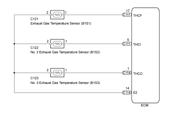
WIRING DIAGRAM
INSPECTION PROCEDURE
- NOTICE:
- Inspect the fuses of circuits related to this system before performing the following inspection procedure.
- After replacing the ECM, the new ECM needs registration (HILUX_TGN26 RM0000012XK070X.html) and initialization (HILUX_TGN26 RM000000TIN057X.html).
- After replacing the fuel supply pump assembly, the ECM needs initialization (HILUX_TGN26 RM000000TIN057X.html).
- After replacing an injector assembly, the ECM needs registration (HILUX_TGN26 RM0000012XK070X.html).
- HINT:
- Read freeze frame data using the intelligent tester. Freeze frame data records the engine condition when malfunctions are detected. When troubleshooting, freeze frame data can help determine if the vehicle was moving or stationary, if the engine was warmed up or not, and other data from the time the malfunction occurred.
- If DTC P242D is stored and the exhaust gas temperature sensor (B1S3) circuit is not malfunctioning, check if the DPF catalytic converter has melted as DTC P242D may be stored when the DPF catalytic converter melts and the exhaust gas temperature sensor (B1S3) is exposed to high temperatures.
| 1.READ VALUE USING INTELLIGENT TESTER (EXHAUST TEMPERATURE) |
Connect the intelligent tester to the DLC3.
Turn the ignition switch to ON and turn the intelligent tester on.
Enter the following menus: Powertrain / Engine and ECT / Data List / Exhaust Temperature B1S1, Exhaust Temperature B1S2 and Exhaust Temperature B1S3.
Read the value.
- Standard:
- Same as the actual exhaust gas temperature (50 to 700°C [122 to 1292°F] during idling after warm-up), and varies after an engine speed of 3000 rpm is maintained for 1 minute.
ResultTemperature Displayed
| Proceed to
|
0°C (32°F) (After warming up the engine)
| A
|
1000°C (1832°F)
| B
|
OK: Same as the actual exhaust gas temperature (50 to 700°C [122 to 1292°F] during idling after warm-up), and varies after maintaining an engine speed of 3000 rpm for 1 minute after accelerating the engine from idling to 3000 rpm
| C
|
- HINT:
- If there is a short circuit, the intelligent tester will indicate 0°C (32°F).
- If there is an open circuit, the intelligent tester will indicate 1000°C (1832°F).
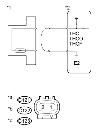
| 2.READ VALUE USING INTELLIGENT TESTER (CHECK FOR OPEN IN WIRE HARNESS) |
Disconnect the C121, C122 or C123 exhaust gas temperature sensor connector.
Connect terminals 1 and 2 of the exhaust gas temperature sensor wire harness side connector.
Connect the intelligent tester to the DLC3.
Turn the ignition switch to ON and turn the intelligent tester on.
Enter the following menus: Powertrain / Engine and ECT / Data List / Exhaust Temperature B1S1, Exhaust Temperature B1S2 and Exhaust Temperature B1S3.
Read the value.
- Standard:
- 1000°C (1832°F)
Text in Illustration*1
| Exhaust Gas Temperature Sensor
|
*2
| ECM
|
*a
| Front view of wire harness connector
(to Exhaust Gas Temperature Sensor (B1S1))
|
*b
| Front view of wire harness connector
(to No. 2 Exhaust Gas Temperature Sensor (B1S2))
|
*c
| Front view of wire harness connector
(to No. 3 Exhaust Gas Temperature Sensor (B1S3))
|
Reconnect the exhaust gas temperature sensor connector.
| 3.REPLACE EXHAUST GAS TEMPERATURE SENSOR |
Replace the exhaust gas temperature sensor (HILUX_TGN26 RM000003TEF00PX.html).
| 4.CHECK HARNESS AND CONNECTOR (EXHAUST GAS TEMPERATURE SENSOR - ECM) |
Disconnect the exhaust gas temperature sensor connector.
Disconnect the ECM connector.
Measure the resistance according to the value(s) in the table below.
- Standard Resistance:
Tester Connection
| Condition
| Specified Condition
|
C122-1 - C111-5 (THCI)
| Always
| Below 1 Ω
|
C122-2 - C114-14 (E2)
| Always
| Below 1 Ω
|
C123-1 - C114-1 (THCO)
| Always
| Below 1 Ω
|
C123-2 - C114-14 (E2)
| Always
| Below 1 Ω
|
C121-1 - C111-17 (THCF)
| Always
| Below 1 Ω
|
C121-2 - C114-14 (E2)
| Always
| Below 1 Ω
|
Reconnect the exhaust gas temperature sensor connector.
Reconnect the ECM connector.
Replace the ECM (HILUX_TGN26 RM0000013Z001HX.html).
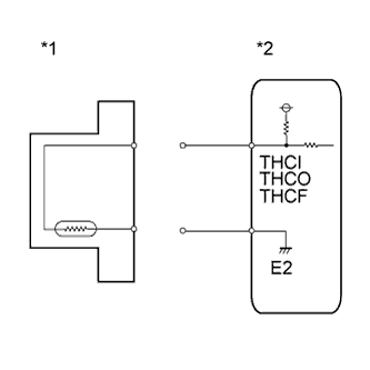
| 6.READ VALUE USING INTELLIGENT TESTER (CHECK FOR SHORT IN WIRE HARNESS) |
Disconnect the C121, C122 or C123 exhaust gas temperature sensor connector.
Connect the intelligent tester to the DLC3.
Turn the ignition switch to ON and turn the intelligent tester on.
Enter the following menus: Powertrain / Engine and ECT / Data List / Exhaust Temperature B1S1, Exhaust Temperature B1S2 and Exhaust Temperature B1S3.
Read the value.
- Standard:
- 0°C (32°F)
Reconnect the exhaust gas temperature sensor connector.
Text in Illustration*1
| Exhaust Gas Temperature Sensor
|
*2
| ECM
|
Reconnect the exhaust gas temperature sensor connector.
| 7.REPLACE EXHAUST GAS TEMPERATURE SENSOR |
Replace the exhaust gas temperature sensor (HILUX_TGN26 RM000003TEF00PX.html).
| 8.CHECK HARNESS AND CONNECTOR (EXHAUST GAS TEMPERATURE SENSOR - ECM) |
Disconnect the exhaust gas temperature sensor connector.
Disconnect the ECM connector.
Measure the resistance according to the value(s) in the table below.
- Standard Resistance:
Tester Connection
| Condition
| Specified Condition
|
C122-1 or C111-5 (THCI) - Body ground
| Always
| 10 kΩ or higher
|
C123-1 or C114-1 (THCO) - Body ground
| Always
| 10 kΩ or higher
|
C121-1 or C111-17 (THCF) - Body ground
| Always
| 10 kΩ or higher
|
Reconnect the exhaust gas temperature sensor connector.
Reconnect the ECM connector.
Replace the ECM (HILUX_TGN26 RM0000013Z001HX.html).
| 10.REPAIR OR REPLACE HARNESS OR CONNECTOR |
Repair or replace the harness or connector.
| 11.CONFIRM WHETHER MALFUNCTION HAS BEEN SUCCESSFULLY REPAIRED |
Connect the intelligent tester to the DLC3.
Clear the DTCs (HILUX_TGN26 RM000000PDK11ZX.html).
Start the engine.
Idle the engine for 3 seconds or more after warming up the engine (the engine coolant temperature is 60°C (140°F) or higher) and allowing 11 minutes to elapse after starting the engine.
Enter the following menus: Powertrain / Engine and ECT / DTC.
Confirm that the DTC is not output again.