Fuel Supply Pump (W/ Dpf) Removal
PRECAUTION
DISCONNECT CABLE FROM NEGATIVE BATTERY TERMINAL
REMOVE RADIATOR ASSEMBLY
REMOVE TIMING BELT
REMOVE ELECTRIC EGR CONTROL VALVE ASSEMBLY WITH NO. 2 EGR VALVE AND EGR COOLER
REMOVE NO. 4 INJECTION PIPE SUB-ASSEMBLY
REMOVE WIRING HARNESS CLAMP BRACKET
REMOVE NO. 2 FUEL PIPE
REMOVE FUEL SUPPLY PUMP ASSEMBLY
Fuel Supply Pump (W/ Dpf) -- Removal |
- NOTICE:
- When replacing the injectors (including shuffling the injectors between the cylinders), common rail or cylinder head, it is necessary to replace the injection pipes with new ones.
- When replacing the fuel supply pump, common rail, cylinder block, cylinder head, cylinder head gasket or timing gear case, it is necessary to replace the fuel inlet pipe with a new one.
- After removing the fuel inlet pipe, clean it with a brush and compressed air.
- NOTICE:
- After turning the ignition switch off, waiting time may be required before disconnecting the cable from the battery terminal. Therefore, make sure to read the disconnecting the cable from the battery terminal notice before proceeding with work (HILUX_TGN26 RM000004QR1006X.html).
| 2. DISCONNECT CABLE FROM NEGATIVE BATTERY TERMINAL |
- NOTICE:
- When disconnecting the cable, some systems need to be initialized after the cable is reconnected (HILUX_TGN26 RM000004QR300CX.html).
| 3. REMOVE RADIATOR ASSEMBLY |
(HILUX_TGN26 RM00000144G01ZX.html)
(HILUX_TGN26 RM00000147C01NX.html)
| 5. REMOVE ELECTRIC EGR CONTROL VALVE ASSEMBLY WITH NO. 2 EGR VALVE AND EGR COOLER |
(HILUX_TGN26 RM000004QWO00GX.html)
| 6. REMOVE NO. 4 INJECTION PIPE SUB-ASSEMBLY |
Remove the bolt, nut and 2 No. 2 injection pipe clamps.
Using a 17 mm union nut wrench, loosen the union nuts and remove the No. 4 injection pipe.
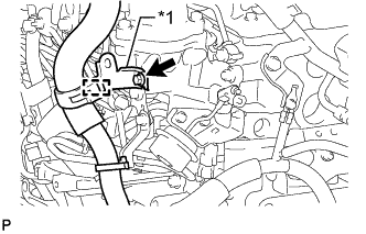
| 7. REMOVE WIRING HARNESS CLAMP BRACKET |
Detach the wire harness clamp.
Text in Illustration*1
| Wiring Harness Clamp Bracket
|
Remove the bolt and wiring harness clamp bracket.
| 8. REMOVE NO. 2 FUEL PIPE |
Using a 6 mm hexagon wrench, remove the supply pump hollow screw and gasket.
Text in Illustration
| Bolt
|

| Supply Pump Hollow Screw
|

| Fuel Check Valve
|

| Union Bolt
|
Remove the fuel check valve, union bolt and 2 gaskets.
Remove the 3 bolts and No. 2 fuel pipe.
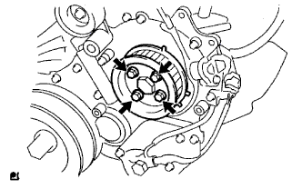
| 9. REMOVE FUEL SUPPLY PUMP ASSEMBLY |
Disconnect the 2 fuel hoses.
Disconnect the fuel temperature sensor connector and suction control valve connector from the fuel supply pump.
Remove the 4 bolts indicated by the arrows in the illustration.
Remove the No. 2 camshaft timing pulley flange and pump drive shaft pulley.
Remove the set nut and O-ring while holding the crankshaft pulley using SST.
- SST
- 09213-58014
09330-00021
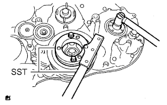
Loosen the 2 nuts.
Using SST, disconnect the fuel supply pump from the injection gear.
- SST
- 09950-50013(09951-05010,09952-05010,09953-05020,09954-05021)
- NOTICE:
- Apply lubricant to the threads and tip of SST (center bolt) before using it.
Remove the 2 nuts and fuel supply pump.
- NOTICE:
- Do not hold or carry the fuel supply pump by the pipe.
- The fuel supply pump must be kept horizontal.
Remove the O-ring.